


Chapter 7 Measuring Waveform
7-52
1. Touch [Measure] to open the Measure dialog box.
2. Touch the Active Channel Selection button, and then select the
channel to be measured.
3. Touch the Measure Item button.
4. Touch [Histogram], or [Amp/Histogram].
5. When selecting [Amp/Histogram], touch the [Histogram] tab.
6. When measuring histogram for time direction, touch [Time] at [Axis].
When measuring histogram for amplitude direction, touch
[Amplitude] at [Axis].
7. Input the value to the histogram marker X1, X2, Y1, and Y2, and
then set the area.
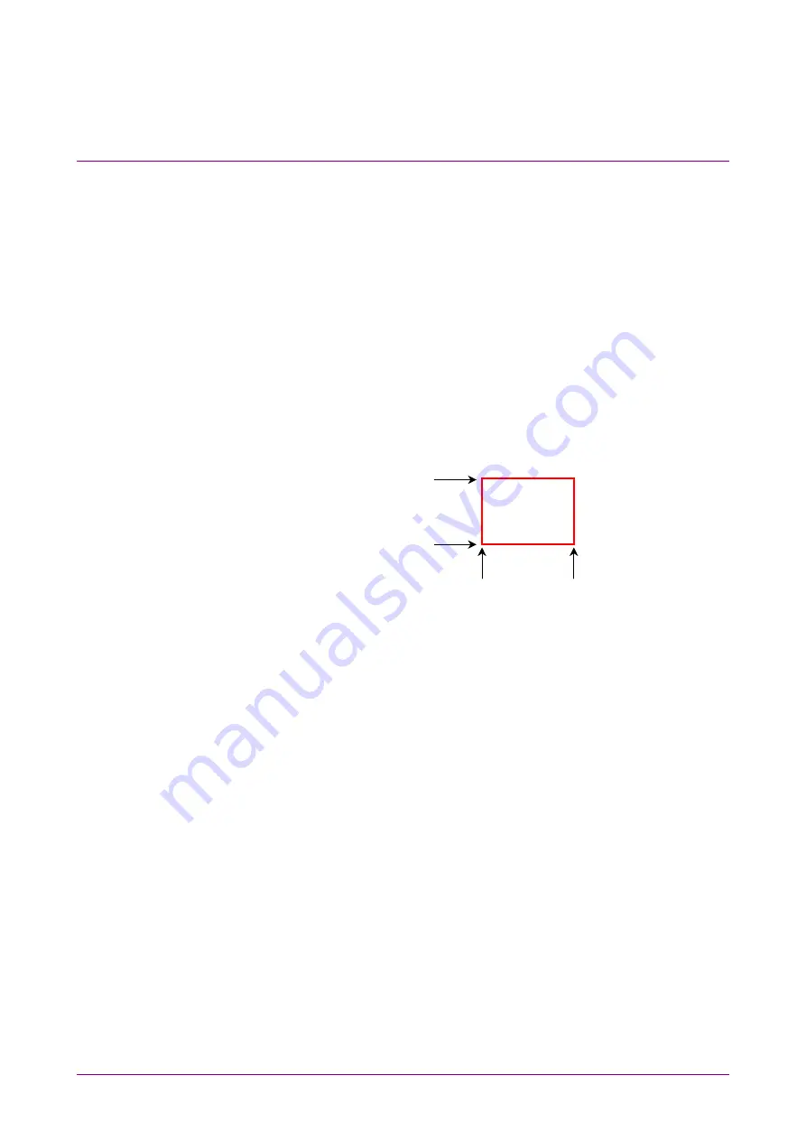
The area border to set the histogram marker is as shown in the
following figure.
Y1
Y2
X1
X2
Toughing the screen and dragging the marker change the histogram
marker position.
8. The measurement result of the data within the area is displayed.
Mean: average
value
std Dev: standard deviation
P-P:
difference between maximum value and minimum value
(Peak to Peak)
Hits:
data count within area
To display marker at screen center:
Touch [Center] at Histogram Marker to center the marker in the middle
of screen.
When histogram measurement is turned on, depending upon the previous
settings, the X and Y coordinates of the histogram window may be set
beyond the boundaries of the current display screen. If this occurs,
touching [Center] at Histogram Marker makes it easy to set the area.
Summary of Contents for BERTWave MP2100B
Page 24: ...xxiv...
Page 96: ...Chapter 2 Before Use 2 42...
Page 112: ...Chapter 3 Connecting with DUT 3 16...
Page 250: ...Chapter 7 Measuring Waveform 7 64 Figure 7 12 1 Marker Display...
Page 262: ...Chapter 7 Measuring Waveform 7 76...
Page 276: ...Chapter 8 Operating Optical Interface 8 14...
Page 304: ...Chapter 9 Performance Test 9 28...
Page 320: ...Chapter 10 Maintenance 10 16...
Page 374: ...Appendix E Performance Test Record Form E 10...
Page 382: ...Index Index 6...