RM0082
Power and clock management
Doc ID 018672 Rev 1
817/844
This technique is easier from a designer prospect for software development and offer a well
known consumption. It is recommended that when performance required is without critical
task and it is sufficient to guarantee an average power computation.
37.2
System control state machine
System control state machine is used to select the input frequency to apply to the system.
Mainly three selections are available:
●
MAIN Oscillator: directly 24 MHz or its ratio (1:2, 1:4, 1:16 or 1:32)
●
RTC Oscillator, if present its 32.768 kHz
●
PLL1 Frequency, generated from MAIN Oscillator
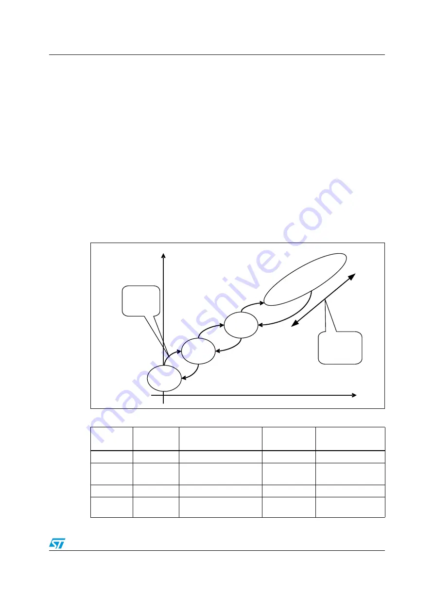
The following sections describe operative System Control State (note that only operating
states are described here, for all intermediate states referred to
See register
Section 14.4.3: SCCTRL register
to change System states.
Figure 108. Operative system control states
Table 736.
Power state for synchronous DRAM system (DRAM clocked by PLL1)
State
ARM
ARM clock
DRAM
Possible code
execution memory
SLEEP
Hibernate
Off
Self refresh
None
DOZE
Running
Running
RTC Osc
MAIN Osc(PLL off)
Self refresh
Self refresh
Internal memory
Internal memory
SLOW
Running
MAIN Osc.(PLLoff)
Self refresh
Internal memory
NORMAL
Running
PLL1 (Up to 333 MHz)
Active
Internal memory and
external DRAM
DOZE
SLOW
SLEEP
NORMAL
Performances
Consumption
IRQ, FIQ
and
RESET
Dynamic
Frequency
Scaling


