11 Buffer Memory (Parameters & Monitored Data)
11.1 Positioning Parameters
205
FX
3U
-20SSC-H Positioning Block User's Manual
11
Buffer
M
e
m
o
ry
12
Pr
ogr
am
Exam
ple
13
D
iagnostics
A
List
of
Par
a
m
e
ter
s and
Da
ta
B
V
e
rs
ion
Infor
m
at
ion
*1.
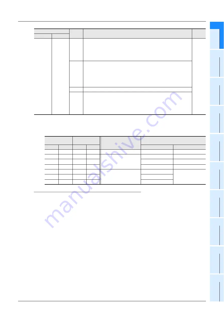
User unit setting
Positioning and speed units are customizable as user units.
The combination of the system of units (b1,b0) and unit setting bits (b3,b2) give the following settings.
→
For details on the user units, refer to Section 7.10
Note
Motor system units and mechanical system units require pulse/feed rate settings.
*2.
The positioning data with position data magnification are as follows:
Example:
The actual address (or travel distance) with target address 1 "123" and position data magnification
"1000" are as follows:
Motor system units:
123
×
1000 = 123000 (pulse)
Mechanical system units, composite system units:
123
×
1000 = 123000 (
µ
m, mdeg, 10
-4
inch)
= 123 (mm, deg, 10
-1
inch)
BFM
#14000
BFM
#14200
b12
DOG switch input logic
Sets DOG switch input logic for 20SSC-H.
1: NC-contact (operates at input OFF)
0: NO-contact (operates at input ON)
→
For details on the DOG mechanical zero return operation,
refer to Subsection 8.1.2
H0000
b13
Count start timing for zero-phase signal
1: DOG forward end (at OFF-to-ON transition of DOG input)
The front end of DOG triggers the zero-phase signal count.
0: DOG backward end (at ON-to-OFF transition of DOG input)
The back end of DOG triggers the zero-point signal count.
→
For details on the DOG mechanical zero return operation,
refer to Subsection 8.1.2
b14
Not available
b15
STOP mode
1: Suspends the operation, and the START command starts the operation for the
remaining travel distance.
0: Ends the operation, canceling the remaining distance. In table operations, operation
is terminated.
→
For details on the stop command, refer to Section 7.4
Unit Setting
Bit Status
System of units
Bit Status
System of units
Unit
b3
b2
b1
b0
Positioning Unit
Speed Unit
-
-
0
0
Motor system units
PLS
Hz
0
0
0
1
Mechanical system units
µ
m
cm/min
0
1
0
1
10
-4
inch
inch/min
1
0
0
1
mdeg
10deg/min
0
0
1
0/1
Composite system units
µ
m
Hz
0
1
1
0/1
10
-4
inch
1
0
1
0/1
mdeg
- Mechanical zero-point address
- Software limit (upper)
- Software limit (lower)
- Target address1
- Target address2
- Target position change value (address)
- Current address (user)
- Current address (pulse)
- Table information (position data)
- Table information (circular data)
BFM Number
Bit
Number
Description
Default
X-axis
Y-axis


