


Chapter 8 Program
8-133
(c) Error state for each axis
According to exercise from “Chapter 8.1.2 Current State Reading,” it is a signal of “Error state” for each axis. It
turns on when an error occurred. Operation will only work when there is no er ror. If you want to operate a
system regardless of errors, you can just inactivate the function.
(d) Address of Positioning Module
In this example, Positioning Module is installed at the 3 slot of 0 bases.
(e) Axis of command execution
You can set an axis for Parameter Setting. XBF-PN04(8)B supports for 4(8) axes. In the “execution of axis”
from the configuration of Parameter Setting, you can set a value for axis1 through axis4(8).
(f) Change Step Number
Set change step number by Current Step Change. XBF-PN04B/PN08B supports 400 step operation data for
each Axis.
Therefore, the range of step number setting of Current Step Change is 1~400. In the example, Axis1 and axis2
are changed to step no.11 and step no. saved in %MW203.
(g) State of Operation complete
If function block is completed without error, “1” will be outputted and m aintain “1” until the next operation. If
error occurred, “0” will be outputted.
(h) Error State
This is the area that output error no. if there are errors in operation of function block.
(i) For more information, reference of Repeat Step No. Change is in the “Chapter 9.5.10.”
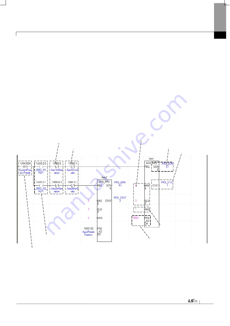
(12) Current Position Preset
(a) This is the condition for Current Position Preset
This is the condition for Current Position Preset Command (XPM_PRS). Once Current Position Preset is
executed, current operation step will move to set step. If the origin has not set yet, the origin would be set to
origin decided.
(b) Axis ready
If communication between the positioning module and the servo driver is normal, corresponding signal will be
on.
(b) Axis ready state
(a) Condition for preset
(c) Operating state
(d) Error state
(e) Position of the module
(h) Completion state
(f) Command axis
(g)Current position to change
(i) Error state
Содержание XBF-PN04B
Страница 1: ...Programmable Logic Controller Positioning Module EtherCAT XGB Series XBF PN04B XBF PN08B ...
Страница 626: ...Chapter 9 Functions BPS37 setup RS232 and PC connection BPS37 option board LED 9 193 ...
Страница 628: ...Chapter 9 Functions c Execute BPS37 set up program and enter the setting values as follows 9 195 ...
Страница 796: ...Appendix3 Dimension A3 1 Appendix 3 Dimension Appendix 3 1 Dimension of XBF PN04B PN08B ...


