


Chapter 8 Program
8-127
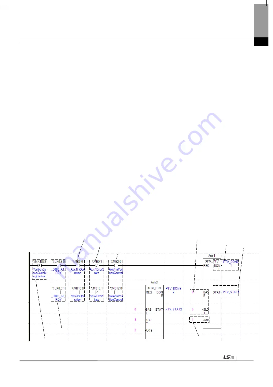
(c) Operation state for each axis
In case that an example program of“8.1.2 Read Current State” is applied, it is a signal showing that each
axis is “operating.” If a r elevant axis is running, it becomes ‘On’. A condition has been s et to make the
control command for position specified speed/position switching valid only when the relevant axis is running.
If the control command for position specified switching is carried out when the relevant axis is not running,
No.301 Error will take place.
(d) Error State for each axis
In case that an example program of“8.1.2 Read Current State” is applied, it is a signal showing “Error State”
for each axis. If any error takes place, it becomes ‘On’. A condition has been s et to perform a c ontrol
command only when there is no er ror with the relevant axis. If the user wants to execute a c ommand
regardless of the occurrence of errors, he/she may remove this condition.
(e) Speed Control Signal for each axis
In case that an example program of“8.1.2 Read Current State” is applied, it is a signal showing each axis is
“controlling its speed.” If the relevant axis is running under speed control, it becomes ‘On.’ A condition has
been set to make the control command for position specified speed/position switching control valid only when
the relevant axis is in a speed control status. If the control command is carried out when the relevant axis is
not in a speed control status, No.302 Error will take place.
(f) Position of a module
For the example program above, it is assumed that positioning modules are installed on NO.0 Base and No.
3 Slot.
(g) Axis to make a command
Decide an axis that will execute the control command. XBF-PN04(8)B can control up to four axes and assign
1 through 4(8) referring to 1-axis through 4(8)-axis for this item.
(h) Transfer amount
After the control command for position specified speed/position control switching is executed, convert from
speed control to position control and moves by transfer amount.
(i) Completion state
If any function block is completely executed without any error, it displays and m aintains “1” until the next
execution while it displays“0” if any error takes place.
(j) Error state
If any error takes place when any function block is executed, this area generates its error number.
(k) For details on the operation of position specified speed/position switching control, refer to “position specified
speed/position switching control”
(6) Position/ Speed Switching Control
(b) Axis ready state
(a) Condition for position/speed switching control
(c) Operating state
(d) Error state
(e) In-position control signal
(g) Command axis
(f) Position of the module
(h) Completion state
(i) Error state
Содержание XBF-PN04B
Страница 1: ...Programmable Logic Controller Positioning Module EtherCAT XGB Series XBF PN04B XBF PN08B ...
Страница 626: ...Chapter 9 Functions BPS37 setup RS232 and PC connection BPS37 option board LED 9 193 ...
Страница 628: ...Chapter 9 Functions c Execute BPS37 set up program and enter the setting values as follows 9 195 ...
Страница 796: ...Appendix3 Dimension A3 1 Appendix 3 Dimension Appendix 3 1 Dimension of XBF PN04B PN08B ...


