


HV100 Series High Performance Current Vector Inverter
66
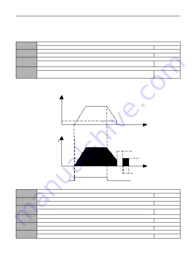
After receiving the shutdown command, the inverter gradually reduces the output frequency according to the
deceleration time, and stops after the frequency drops to zero. If the shutdown DC braking function is valid, the DC braking
process will be executed after reaching the shutdown DC braking start frequency (according to 01.09 setting, a shutdown
DC braking waiting time may be required), and then the shutdown will be performed.
1
:
Free stop
After receiving the shutdown command, the inverter immediately terminates the output, and the load stops freely
according to the mechanical inertia.
01.09
Start frequency of DC braking during stop
0.00 ~ [00.13] upper limit frequency
0.00
01.10
Waiting time for DC braking during stop
0.0
~
100.0s
0.0
01.11
DC braking current during stop
0.0 ~ 150.0% * rated current of motor
0.0%
01.12
Time for DC braking during stop
0.0: DC brake does not operate
0.1
~
100.0s
0.0
The set value of DC braking current during shutdown is a percentage relative to the rated current of the inverter. When
the stop braking time is 0.0s, there is no DC braking process. As shown in the figure below:
Figure 01-4 Diagram of shutdown DC brake
01.13
Acceleration time 2
0.1
~
3600.0
Type setting
01.14
Deceleration time 2
0.1
~
3600.0
Type setting
01.15
Acceleration time 3
0.1
~
3600.0
Type setting
01.16
Deceleration time 3
0.1
~
3600.0
Type setting
01.17
Acceleration time 4
0.1
~
3600.0
Type setting
01.18
Deceleration time 4
0.1
~
3600.0
Type setting
Four groups of acceleration and deceleration time can be defined and can be controlled by different groups of terminals
To select the acceleration and deceleration time 1 ~ 4 during the operation of the inverter, please refer to the definition of
the terminal function of increasing deceleration time 07.00 ~ 07.06.
Output
Frequency
Stop braking start
frequency
Output current
(effective)
Stop braking waiting time
DC braking capacity
Stop braking time
Run Command


