


HV100 Series High Performance Current Vector Inverter
76
05.05
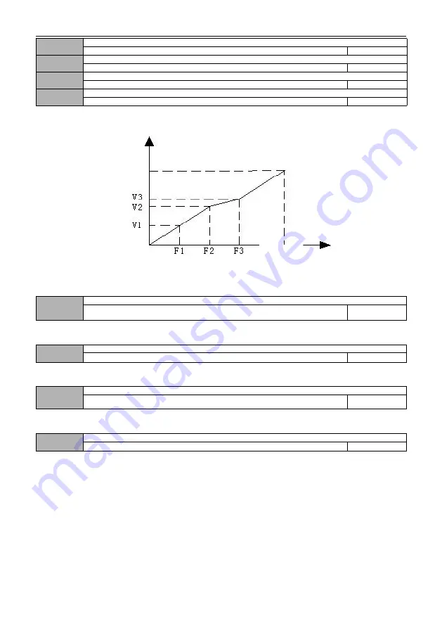
V/F frequency value F2
Frequency value 01 ~ frequency value F3
25.00
05.06
V/F Voltage value V2
Voltage value v1 ~ voltage value V3
50.0%
05.07
V/F frequency value F3
Frequency value F2 ~ rated frequency of motor
37.50
05.08
V/F Voltage value V3
Voltage value v2 ~ 100.0% * rated voltage of motor
75.0%
Schematic diagram of voltage and frequency is as follows:
Figure F5-3 Schematic diagram of V/F curve set by users
05.09
V/F control slip frequency compensation
0.0 ~ 200.0% * rated slip
0.0%
The speed of asynchronous motor will decrease after being loaded. Slip compensation can make the speed of motor
close to its synchronous speed, thus making the speed control accuracy of motor higher.
05.10
V/F control slip frequency filter coefficient
1
~
10
3
This parameter is used to adjust the response speed of slip frequency compensation. The larger the setting of this
value, the slower the response speed and the more stable the motor speed.
05.11
V/F control torque frequency compensation filter coefficient
0
~
10
Model setting
When the free torque increases, this parameter is used to adjust the response speed of torque compensation. The
larger this value is, the slower the response speed and the more stable the motor speed.
05.12
Selection of separate V/F control
0
~
3
0
0: VF semi-separated mode, voltage open loop output
In this control mode, the inverter starts according to the normal V/F curve, and then adjusts the voltage to the set target
voltage value after reaching the set frequency point. In this mode, the voltage has no feedback, and the target voltage
value is set as an open loop. As shown in the figure.
Voltage
Maximum
output
voltage
Maximum
output
frequency
Frequency


