HV100 Series High Performance Current Vector Inverter
62
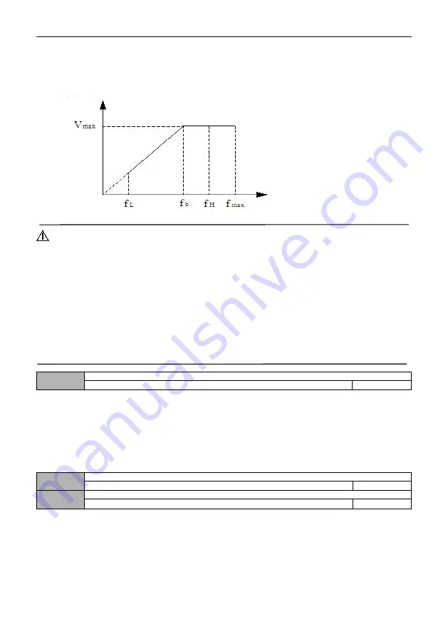
The maximum output frequency is the highest frequency allowed by the inverter, which is the benchmark for setting
acceleration and deceleration time, as shown in the figure fmax below. The basic operating frequency is the minimum
frequency corresponding to the highest voltage output by the inverter, which is generally the rated frequency of the motor,
as shown in the figure below. The maximum output voltage Vmax is the corresponding output voltage when the inverter
outputs the basic operating frequency, which is generally the rated voltage of the motor; Vmax
;
as shown in the following
figure; FH and FL are defined as upper limit frequency and lower limit frequency respectively, as shown in Figure 00-1:
Figure 00-1 Schematic diagram of voltage and frequency
Notes:
1. The maximum output frequency, upper limit frequency and lower limit frequency should be carefully set according to the
nameplate parameters and operating conditions of the actual controlled motor, otherwise the equipment may be damaged.
2. The limit range of upper frequency is valid for JOG operation, while the limit range of lower frequency is invalid for JOG
operation.
3. In addition to the upper limit frequency and the lower limit frequency, the output frequency of the inverter during
operation is also limited by the set values of parameters such as starting frequency, starting frequency of DC braking during
shutdown and jumping frequency.
4. The relationship among maximum output frequency, upper limit frequency and lower limit frequency is shown in the
above figure 00-1. Please pay attention to the order of magnitude when setting.
5. The upper and lower limit frequencies are used to limit the actual output frequency of the motor. If the set frequency is
higher than the upper limit frequency, it will run at the upper limit frequency; Run at the lower limit frequency if the set
frequency is lower than the lower limit frequency (the running state when the set frequency is lower than the lower limit
frequency is also related to the setting of function code 01.31); If the set frequency is less than the starting frequency, it will
run at zero frequency when starting.
00.15
Frequency output mode
0000
~
011
0000
LED single digit: high and low frequency mode selection
0: Low frequency mode (0.00
~
300.00HZ)
1: High frequency mode (0.0
~
300.0HZ)
LED 10-digit: acceleration and deceleration reference selection
0: Maximum output frequency as the reference
1: Target output frequency as the reference
LED 100-digit: reserved
LED 1000-digit: reserved
The high frequency mode is only effective for V/F control
00.16
Acceleration time 1
0.1
~
3600.0S
Model setting
00.17
Deceleration time 1
0.1
~
3600.0S
Model setting
The acceleration time refers to the time required for the inverter to accelerate from zero frequency to the maximum
output frequency, as shown in the figure below at t1. Deceleration time refers to the time required for the inverter to
decelerate from the maximum output frequency to zero frequency, t2 as shown in the figure below.
There are four groups of acceleration and deceleration time parameters of this series of inverters, and the acceleration and
deceleration time of the other three groups is defined in the function codes 01.13 ~ 01.18. The factory default acceleration
and deceleration time is determined by the model. If you want to select other acceleration and deceleration time groups,
please select them through the multi-function terminal (please refer to the function codes 07.00 ~ 07.06). The acceleration
and deceleration time of JOG operation are defined separately in 01.22 and 01.23.
Output frequency
Output voltage


