


HV100 Series High Performance Current Vector Inverter
109
Actual length = calculated length × Length magnification ÷ Length correction factor
When the actual length (09.69) ≥ the set length (09.68), the inverter will automatically issue a shutdown instruction to stop.
The actual length (09.69) should be cleared or modified before running again < Set the length (09.68), otherwise it will not
start.
Tips
:
The actual length can be cleared with multi-function input terminal (the input terminal is defined as 46 functions, and
the length count is cleared). If the terminal is valid, the previous length count value will be cleared, and the actual length
can be counted and calculated normally after the terminal is disconnected.
The actual length is 09.69, which is automatically stored when power is cut off.
When the set length 09.68 is 0, the fixed-length shutdown function is invalid, but the length calculation is still valid.
Application example of fixed-length shutdown function:
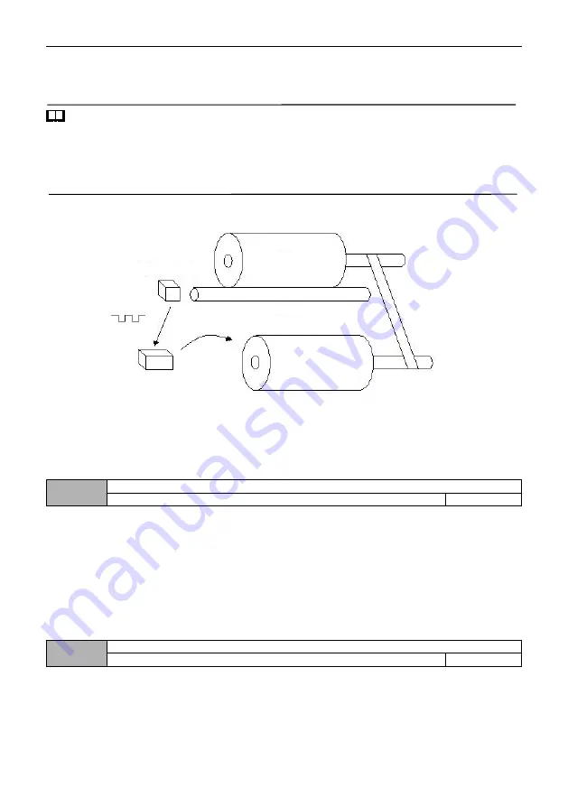
Figure F9-7 Example of Long Stop Function
In Figure F9-7, the inverter drives the motor, which drives the spindle shaft to rotate through the conveyor belt, and
the speed measuring shaft contacts the spindle, so that the linear speed of the spindle is detected and transmitted to the
inverter through the counting terminal in the form of pulses. The inverter detects the pulses and calculates the actual length.
When the actual length is greater than or equal to the set length, the inverter automatically stops.
010 Group- Protective parameters
10.00
Motor Overload protection selection
0
~
2
1
0: prohibited
No motor overload protection (use it with caution).
1: Ordinary motor (electronic thermal relay mode, low-speed compensation)
due to the poor heat dissipation effect of ordinary motor in low-speed operation, the corresponding motor thermal
protection
value should also be adjusted appropriately. The low-speed compensation characteristic
here is to lower the overload protection threshold of motor whose operating frequency is lower than 30Hz.
2. Variable frequency motor (electronic thermal relay mode, low speed without compensation)
Due to the heat dissipation of the frequency conversion special motor is not affected by the rotating speed, there is no
need to adjust the protection value during low-speed operation.
10.01
Motor overload protection coefficient
20.0%
~
120.0%
100.0%
To implement valid overload protection for different types of load motors, it is necessary to set the overload protection
coefficient of motors reasonably and limit the maximum current allowed by the inverter. The motor overload protection
coefficient is the percentage of the rated current value of the motor to the rated output current value of the inverter.
When the inverter drives the motor with matching power level, the motor overload protection coefficient can be set to
100%. As shown in the figure below:
Spindle
Speed sensor
Speed measuring shaft
Motor
Inverter


