HV100 Series High Performance Current Vector Inverter
77
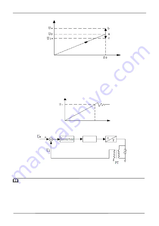
Figure F5-4 Voltage Control Mode 0
F0—— set frequency, V0—— rated voltage corresponding to set frequency, U */U1 * —— set value of a given channel in
05.13.
As shown in the above figure, after the frequency of point A is stabilized, the voltage adjustment begins. According to
the target voltage value and the input voltage, the voltage point may move to point b (increase) or point c (decrease) until it
reaches to the target value.
1: VF semi-separated mode, voltage closed loop output
The only difference between this mode and mode 0 is that it introduces a voltage closed loop, which can stabilize the
voltage by PI adjustment for the deviation between the feedback voltage and the given voltage. It can compensate the
target voltage deviation caused by load change, and make the voltage control precision higher and the response faster, as
shown in the following figure
Figure F5-5 Voltage Control Mode 1
This control method is widely used in EPS power supply and other fields, and its control principle block diagram is as
follows:
U*—— set value of a given channel in 05.13
U1——analog feedback voltage value (PT)
PT—— Electric quantity transmitter
Figure F5-6 EPS control principle
Tips
:
The corresponding relationship between analog feedback channel voltage and actual voltage from 06.06 to 06.11 is
uniquely determined by the voltage transmitter (PT), and its calculation method is as follows:
Assume that U * = 120% * Ue = 456 V (AI1 setting )
PT transformation ratio =50 (input AC 0-500V, output DC 0-10V)
Then when the output reaches to the target voltage of 456V, the feedback voltage of PT output is
456/50V=9.12V
When the upper limit input of AI1 is 10V, the determined input voltage is 500V, and the ratio relative to the rated voltage is
500/380=132%
Therefore, 06.09(AI2 input upper limit voltage) is set to 10.00V, and 06.10(AI2 upper limit corresponding setting) is set to
132%.
Output
frequency
Output
voltage
Output
voltage
Time
LC Filter


