


HV100 Series High Performance Current Vector Inverter
90
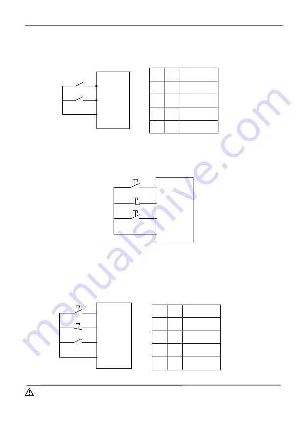
1: Two-wire control mode 2
Xm: forward command (FWD),Xn: Reverse command (REV), Xm and Xn represent any two terminals respectively
defined as FWD and rev functions in DI1-HDI. In this control mode, K1 is the running and stopping switch, and K2 is the
direction change switch.
K1
K2
Xm
(
FWD)
Xn(REV)
COM
Figure F7-3 Schematic diagram of two-wire control mode 2
2
:
Three-wire control mode 1
Xm: forward command (FWD), Xn: reverse command (REV), Xx: shutdown command, Xm, Xn and Xx represent any
three terminals respectively defined as FWD, REV and three-wire operation control functions in DI1-HDI. The connected
K1 and K2 are invalid before K3 is connected. When K3 is connected, K1 is triggered, and the inverter rotates forward.
When triggering K2, invert rotates reversely; When disconnecting K3, the inverter stops.
COM
Xn(REV)
Xx
Xm
(
FWD
)
K3
K1
K2
Figure F7-4 Schematic diagram of three-wire control mode 1
3: Three-wire control mode 2
Xm: running command, Xn: running direction selection, Xx: shutdown command, Xm, Xn and Xx represent any 3
terminals respectively defined as FWD, REV and three-wire operation control functions in DI1-HDI. The connected K1 and
K2 are invalid before K3 is connected. When K3 is connected, K1 is triggered, and the inverter rotates forward; When
triggering K2 alone, it is invalid; After K1 triggers the operation, K2 is triggered again, and the running direction of the
inverter is switched. When disconnect K3, the inverter stops.
K1
K3
K2
Xm(FWD)
Xx
Xn(REV)
COM
Figure F7-5 Schematic diagram of three-wire control mode 2
Notes:
When the three-wire control mode 2 is running in forward rotation, the terminal defined as REV can stably reverse
when it is closed, and when it is disconnected, it will return to forward rotation.
K2
K1
Running
instructions
0
0
Stop
0
1
Forward
1
0
Stop
1
1
Reverse
K2
K1
Running
instructions
0
0
Stop
0
1
Forward
1
0
Reversal
1
1
Stop


