


HV100 Series High Performance Current Vector Inverter
72
2. Condition effective(terminal switching)
The control object without PG current vector control is controlled by the switch input terminal (DI) defined as speed and
torque control switching. Please refer to function description No.48 of 07 parameter group, DI terminal function.
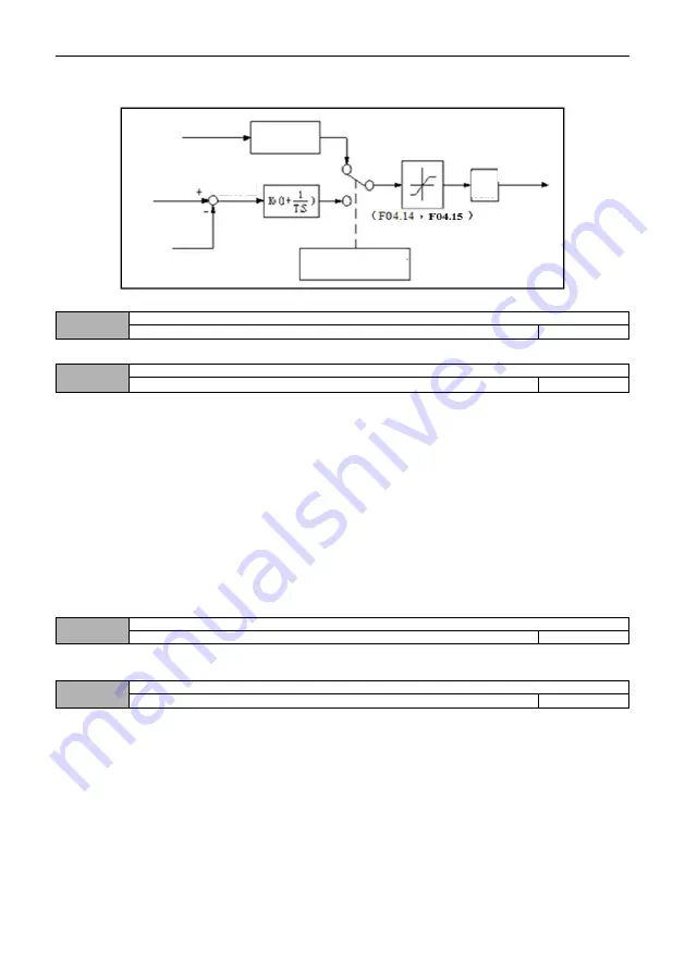
Fig. F4-2 simplified block diagram of torque control
04.11
Speed and torque switching delay
0.01
~
1.00S
0.05
This function code defines the delay time when switching torque and speed mode.
04.12
Torque command selection
0
~
3
0
This function code sets the torque given channel during torque control.
0
:
Keypad digit given
Torque commands are given by keypad digit. See 04.13 settings for setting values.
1
:
AI1
Torque command is set by analog input AI1. The positive and negative input of AI1 corresponds to the torque
command value in the positive and negative directions.
When using this function, users need to set the physical quantity corresponding to AI1 input as torque instruction, and
also set the corresponding curve of AI1 and the filtering time of AI1 input. Please refer to the description of function code
06.00 ~ 06.05.
2
:
AI2
Torque command is set by analog input AI1. The positive and negative input of AI1 corresponds to the torque
command value in the positive and negative directions.
When using this function, users need to set the physical quantity corresponding to AI1 input as torque instruction, and
also set the corresponding curve of AI1 and the filtering time of AI1 input. Please refer to the description of function code
06.06 ~ 06.11.
3: Communication given
Torque instruction is given by RS485 communication.
04.13
Keyboard digital setting torque
-200.0% ~ 200.0% * rated current of motor
0.0%
The set value of this function code corresponds to the torque instruction, and is selected as the torque set value given
by keypad digit.
04.14
Speed limit channel selection 1 for torque control mode (forward direction)
0
~
2
0
This function code sets the forward speed limit channel during torque control.
0
:
Keypad digit given 1
See 04.16 Settings for details.
1
:
AI1
The forward speed limiting channel in torque control is given by AI1. Please refer to the description of function code
06.00 ~ 06.05.
2
:
AI2
The forward speed limiting channel during torque control is given by AI2. Please refer to the description of function
code 06.06 ~ 06.11.
Outpu
t filter
Torque
current
given
The external
torque command Primary delay
filtering
Actual Speed (Speed
Limit Value)
Speed Limit
Value
Speed
Error
Actual
Speed


