


HV100 Series High Performance Current Vector Inverter
99
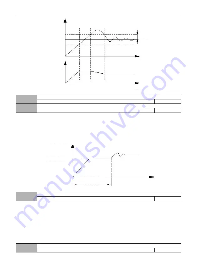
Figure F8-3 Schematic diagram of deviation limit
08.10
Closed loop preset frequency
0.00 ~ upper limit frequency
0.00
08.11
Preset frequency holding time
0.0
~
3600.0s
0.0
This function code defines the frequency and running time of inverter before PID is put into operation when PID control
is valid. In some control systems, in order to make the controlled object reach the preset value quickly, the inverter forcibly
outputs a certain frequency value of 08.10 and a frequency holding time of 08.11 according to the setting of this function
code. That is, when the control object is close to the control target, the PID controller is put into operation to improve the
response speed. As shown in the figure below:
Figure F8-4 Schematic diagram of closed-loop preset frequency operation
08.12
Sleep mode
0
~
2
1
0: Invalid
1: Sleep when feedback pressure exceeds or falls below sleep threshold
This mode is the first sleep mode of PID, as shown in Figure F8-5
2: Sleep when feedback pressure and output frequency are stable
This mode is the second sleep mode of PID. There are two situations (as shown in Figure F8-6):
1) if the feedback value is less than the given value and greater than the given value *(1-set deviation [08.14]), the
change of output frequency is within 6%, and then sleep after the sleep delay time [08.17].
2) If the feedback value rises above the given value, keep the sleep delay time [08.17] and then go to sleep. On the
contrary, if the feedback value drops below the awakening threshold [08.16], wake up immediately.
08.13
Selection of sleep shutdown mode
0
~
1
0
Given
quantity
Output
frequency
Feedback
quantity
Deviation limit
Time
Time
Output frequency
Time
Preset frequency
Preset frequency
Holding time


