


GD32F20x User Manual
495
NERR) in USART_STAT0.
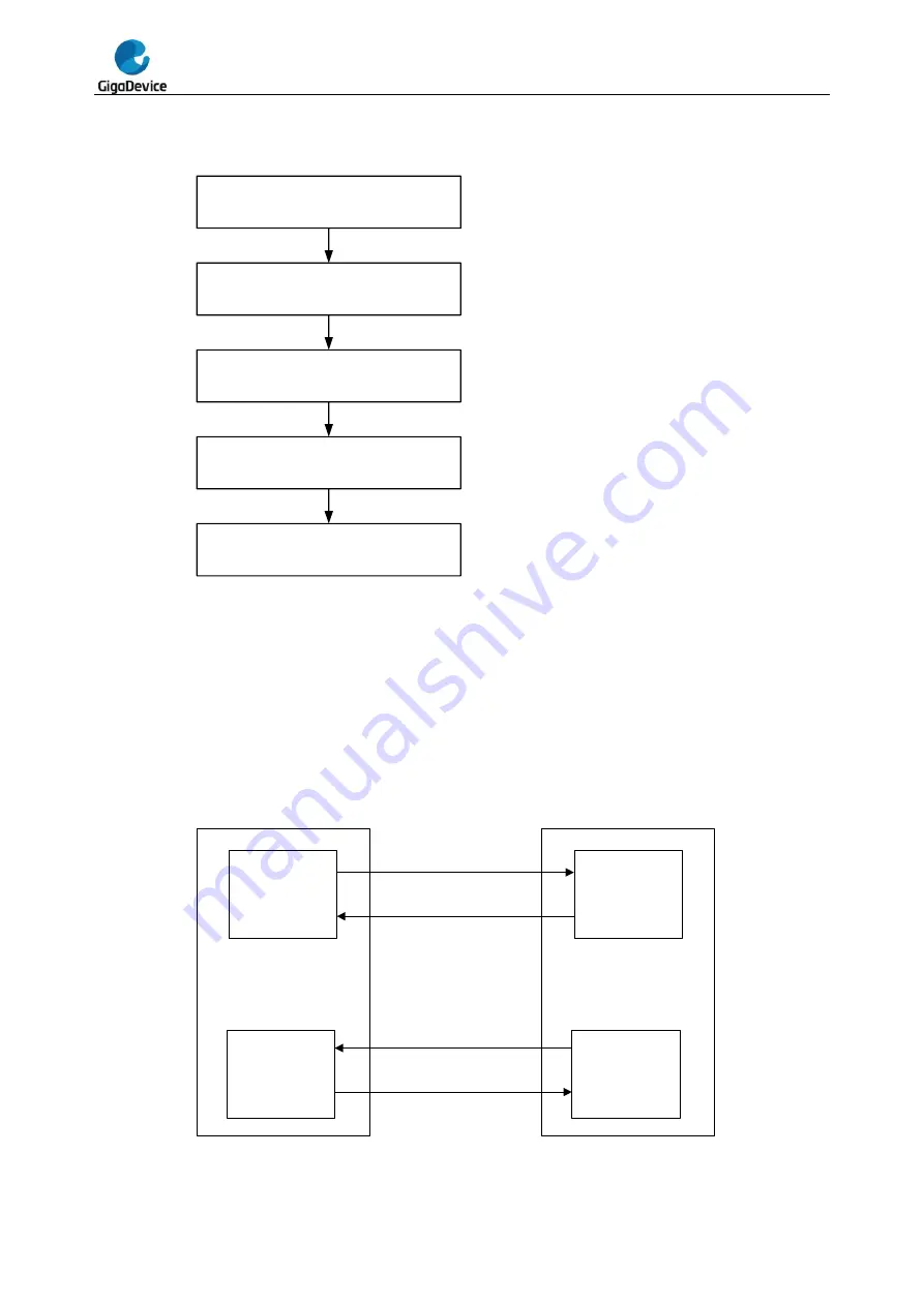
Figure 19-6. Configuration step when using DMA for USART reception
Set the address of USART_DATA as the
DMA source address
Set the address of the buffer in internal
sram as the DMA destination address
Set the number of data as the DMA
transfer number
Set other configurations of DMA,
interrupt enable, priority, etc
Enable the DMA channel for USART
.
When the number of the data received by USART reaches the DMA transfer number, an end
of transfer interrupt can be generated in the DMA module.
19.3.6.
Hardware flow control
The hardware flow control function is realized by the nCTS and nRTS pins. The RTS flow
control is enabled by writing ‘1’ to the RTSEN bit in USART_CTL2 and the CTS flow control
is enabled by writing
‘1’ to the CTSEN bit in USART_CTL2.
Figure 19-7. Hardware flow control between two USARTs
USART 1
TX module
RX module
USART 2
RX module
TX module
TX
RX
nCTS
nRTS
RX
TX
nRTS
nCTS
Содержание GD32F20 Series
Страница 1: ...GigaDevice Semiconductor Inc GD32F20x ARM Cortex M3 32 bit MCU User Manual Revision 2 2 Oct 2019 ...
Страница 191: ...GD32F20x User Manual 191 Bits Fields Descriptions 31 0 TRNDATA 31 0 32 Bit Random data ...
Страница 290: ...GD32F20x User Manual 290 conversion is ongoing ...
Страница 325: ...GD32F20x User Manual 325 15 0 ALRM 15 0 RTC alarm value low ...
Страница 385: ...GD32F20x User Manual 385 ...
Страница 523: ...GD32F20x User Manual 523 clears AERR bit by writing 0 to it ...


