YOKOGAWA AQ7260 OTDR User Manual Download Page 220

Chapter 4  ENTERING CHARACTERS 


4-5


10.

   Press  [ENTER]. 

11.

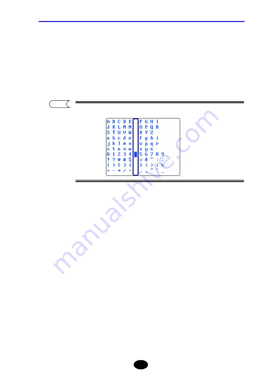
   Locate the character cursor to “0” by using the arrow key. 

12.

   Press  [ENTER]. 

13.

   Locate the character cursor to “space” by using the arrow key. 


A space is provided for each line. 


14.

   Press  [ENTER]. 

15. 

Locate the character cursor to “O” by using the arrow key. 

16.

   Press  [ENTER]. 

17.

   Locate the character cursor to “T” by using the arrow key. 

18.

   Press  [ENTER]. 

19.

   Locate the character cursor to “D” by using the arrow key. 

20.

   Press  [ENTER]. 

21.

   Locate the character cursor to “R” by using the arrow key. 


TIP 

Summary of Contents for AQ7260 OTDR

Page 1: ...User s Manual Y okogawa Electric Corporation AQ7260 OTDR IM 813920300 01E 2nd Edition ...

Page 2: ...ware version refer to page 10 4 yThe instrument uses Linux and Microwindows Linux is a trademark or a registered trademark of Linus Torvalds in U S A and other countries y This product includes open source software For the procedure of obtaining the source code contact your nearest YOKOGAWA dealer Copying or reproduction of all or any part of the contents of this manual without permission is stric...

Page 3: ...t are carried out according to its quality assurance system However should breakdown occur arising from defects in manufacturing or accidents during transport please contact the agent from whom the product was purchased y Recommended recalibration period is 1 year Inquiry of about recalibration please contact the agent from whom the instrument was purchased y The following parts are consumable par...

Page 4: ...andling WARNING Indicates a potentially hazardous situation that may possibly result in death or serious injury in the event of improper handling CAUTION Indicates a potentially hazardous situation that may result in moderate injury or property damage in the event of improper handling The degree of danger and damage is indicated by the following graphic symbols U indicates a warning or caution Thi...

Page 5: ...alled a TIP mark It indicates information that is useful for operation of the instrument This is called a reference mark It indicates the reference page for the contents or terms used in this manual The following symbols are used on this instrument Caution TIP Refer Direct current Alternating current Danger Caution Danger risk of electronic shock Equipment protected throughout by DOUBLE INSULATION...

Page 6: ...deviations pursuant to Laser Notice No 50 dated May 27 2001 Optical module AQ7261 AQ7264 Laser type FP Laser InGaAsP FP Laser InGaAsP Laser class 1M 1M Center wavelength 1310nm 1550nm 1310nm 1550nm CW 1mW 1310nm 1550nm Output power PULSE 100mW 1310nm 1550nm 100mW 1310nm 1550nm PULSE WIDTH 20µs 1310nm duty 1 6 20µs 1550nm duty 1 6 20µs 1310nm duty 1 6 20µs 1550nm duty 1 6 50µs 1550nm duty 0 8 Optic...

Page 7: ...ams enter the eyes they may be seriously damaged resulting in excessive deterioration of eyesight To prevent such accidents the following points must be strictly observed Never emit laser beam if no optical fiber is connected to the emitter section When disconnecting the optical fiber from the emitter section stop emission first While laser beam is output never stare into the emitter section nor t...

Page 8: ...h the instrument Battery pack Model name 3UR18650F 2 For details on use of power supply refer to page 3 3 Before connecting the instrument to the power read the safety precautions given below AC adapter CAUTION Do not connect or disconnect the power cord while the instrument is powered ON Doing so may result in breakdown Refer ...

Page 9: ...an water such as tap water never rub the eyes and consult a doctor Failure to do so may cause damage to the eyes The instrument and battery pack must be kept out of the reach of children If the battery fluid leaks and adheres to skin or clothes immediately wash with clean water such as tap water Adhesion to the skin may produce irritation ...

Page 10: ...g or it gets damaged causing charging with abnormal current or voltage Such charging may cause a chemical reaction inside the battery pack resulting in battery fluid leakage heat generation smoke explosion or fire Charging of the battery pack must be performed on this instrument under the specified charging conditions If charging is performed in an environment that does not conform to the specifie...

Page 11: ...tery fluid leakage heat generation smoke explosion or fire Do not use or leave the battery pack in strong direct sunlight or in places like inside an automobile under very strong sunshine Doing so may result in battery fluid leakage heat generation or smoke It also may deteriorate the performance or life of the battery pack The battery pack has a built in protective circuit designed to prevent dan...

Page 12: ... Take care not to let water enter the instrument or to allow it to get wet Failure to observe this may result in fire electric shock or breakdown Restrictions Regarding Operating Conditions WARNING The power cord specified by YOKOGAWA must be used Use of any other power cord may result in fire electric shock or accident ...

Page 13: ...xpose the instrument to water splashes Failure to observe this may result in electric shock fire or accident Do not allow the terminals to short circuit Failure to observe this may result in fire or breakdown When using an AC adapter make sure that it is inserted into the AC outlet properly If the power plug comes into contact with metal objects fire or electric shock may result When carrying out ...

Page 14: ...oing so may result in electric shock or breakdown Do not place the instrument on an unstable surface like a shaky table or slope The instrument may drop or turn over causing injury Do not place the instrument in areas where there is excessive vibration or impact The instrument may drop or turn over causing injury When disconnecting the power cord always hold the plug and pull it out Pulling the po...

Page 15: ...RNING CAUTION must be strictly observed WARNING Do not leave metal objects or containers of liquid such as water near the instrument Strong wind may turn over the container spilling the water or cause metal objects to hit the instrument resulting in fire electric shock or breakdown Do not modify the power cord bend twist or pull it excessively Failure to observe this may result in fire or electric...

Page 16: ...be guaranteed Do not allow short circuiting of the battery pack s terminals with metal objects Failure to observe this may result in fire or breakdown If this instrument is used in a manner not specified in this manual the protection provided by this instrument may be impaired Notes on Maintenance and Inspection Periodic maintenance and inspection of the instrument are recommended For enquiries re...

Page 17: ...nstrument was purchased Continuing to use it may result in fire electric shock or breakdown Should smoke or odd smells be detected turn OFF the power switch on the instrument disconnect the power plug from the AC outlet and then contact your agent from whom the instrument was purchased Failure to observe this may result in fire electric shock or breakdown If the power cord is damaged contact the a...

Page 18: ... The life of the battery is approximately five years For details on replacement of the backup battery refer to page 1 25 Notes on LCD Panel CAUTION This instrument uses a liquid crystal display panel The display panel gradually becomes unclear due to the backlight life The LCD panel needs to be replaced when it becomes unclear The life of the LCD panel is approximately three years Please contact t...

Page 19: ...measurement results automatically at the end of measurement This chapter explains how to edit the detection results Chapter 6 FILE OPERATION Explains how to use e g open delete files saved to a storage medium Chapter 7 USING USEFUL FUNCTIONS This instrument has various useful functions This chapter explains these functions Chapter 8 USING OPTIONS AND EXTERNAL DEVICES Explains how to use options an...

Page 20: ...III Chapter 2 BEFORE STARTING MEASUREMENT XVIII Chapter 3 PERFORMING MEASUREMENTS XVIII Chapter 4 ENTERING CHARACTERS XVIII Chapter 5 EDITING AUTOMATIC SEARCH RESULTS XVIII Chapter 6 FILE OPERATION XVIII Chapter 7 USING USEFUL FUNCTIONS XVIII Chapter 8 USING OPTIONS AND EXTERNAL DEVICES XVIII Chapter 9 SPECIFICATIONS XVIII Chapter 10 APPENDIX XVIII Contents XIX Chapter 1 BEFORE USING THE INSTRUMEN...

Page 21: ...1 23 1 9 Replacing the Backup Battery 1 25 1 10 Names of Instrument Parts 1 28 Front View 1 28 Rear View 1 30 Top View 1 32 Right Side View 1 33 Accessories 1 34 Options 1 35 1 11 Screen Display 1 36 Description of Screen Display 1 36 Meaning of Each Part of the Trace 1 40 1 12 Notes Before Performing Measurement 1 42 When Using AQ7261 AQ7264 AQ7265 1 42 Chapter 2 BEFORE STARTING MEASUREMENT 2 1 2...

Page 22: ...tore the File Step 5 3 53 3 7 Measuring an Optical Fiber Step 6 3 54 Performing Real Time Measurement 3 55 Performing Average Measurement 3 56 When the Trace Contains a Lot of Noise 3 59 3 8 Checking the Measured Data Step 7 3 64 Basic Operations 3 64 When AUTO is Selected for EVENT SEARCH 3 68 When MANUAL is Selected for EVENT SEARCH 3 71 3 9 Recording the Measured Data Step 8 3 88 Saving the Mea...

Page 23: ...rinting a File 6 12 Copying a File 6 18 6 2 Using the Utility Functions 6 22 Initializing a Drive 6 23 Deleting a Folder 6 25 Creating a Folder 6 27 Copying a Folder 6 30 Chapter 7 USING USEFUL FUNCTIONS 7 1 7 1 Initializing the Vertical Horizontal Axis Scales 7 2 7 2 Displaying Approximate Lines 7 3 For Traces that Have Been Auto Searched 7 4 For Traces that Have Not Been Auto Searched 7 6 7 3 Us...

Page 24: ...r 7 51 Turn off a Laser 7 51 7 12 Making a Measurement Continuously Changing the Wavelengths 7 52 Chapter 8 USING OPTIONS AND EXTERNAL DEVICES 8 1 8 1 Using Options 8 2 Option Unit 8 3 8 2 Using External Devices 8 9 USB Keyboard 8 10 PCMCIA Memory Card 8 13 USB Printer 8 16 USB Storage Medium 8 21 8 3 Operating the Instrument from a Personal Computer 8 22 Operation by using RS 232C 8 23 Operation ...

Page 25: ... scattering ray 10 8 Connection point 10 9 Dead zone 10 9 Distance measuring accuracy 10 9 Distance range 10 9 Dynamic range 10 10 Event dead zone 10 10 Event list 10 10 Event note 10 10 Far end 10 11 Fault location 10 11 Filter 10 11 Format 10 11 Fresnel reflection 10 11 Group index 10 12 Label 10 12 Least squares approximate LSA 10 12 Near end 10 12 OTDR 10 12 Pulse width 10 13 Real time measure...

Page 26: ...CONTENTS XXV Secondary reflection 10 15 Spatial resolution 10 15 Splice loss 10 15 Two Point Approximate TPA 10 15 ...

Page 27: ......

Page 28: ...y 1 7 1 4 Daily Maintenance 1 8 1 5 Replacing the Optical Module 1 12 1 6 Replacing the Optical Adapter 1 16 1 7 Replacing the Battery Pack 1 19 1 8 Charging the Battery Pack 1 23 1 9 Replacing the Backup Battery 1 25 1 10 Names of Instrument Parts 1 28 1 11 Screen Display 1 36 1 12 Notes Before Performing Measurement 1 42 ...

Page 29: ... loss effectively by detecting back scattering rays caused by Rayleigh scattering inside the fiber and rays reflecting at connection points and fault points Since the optical section comes in a module an appropriate optical module can be selected according to the wavelength and type of optical fiber to be used This instrument also can be used for light source depend on the mounted optical module ...

Page 30: ...he appearance operation of each switch and connector and check for any damage or defects that might have occurred during transport In addition check that all the accessories are present and correct It is recommended that packing materials such as corrugated boxes and cushioning materials be kept in a safe place so that they can be reused when transporting the instrument again Operation Inspection ...

Page 31: ...mperature humidity does not change excessively throughout the day Areas where the instrument will not be exposed to direct sunlight Areas where there is little dust Low humidity areas where no water drops are generated or collect on the instrument Areas where the instrument will not be exposed to active gases or oxidized If you are not going to use the instrument for a long period of time store it...

Page 32: ...ottom front rear right left panels and the sides of the box 4 Put shock absorbent materials at the bottom of the box to absorb shocks such as vibration 5 Place the instrument in the center of the box and fill the spaces between the box s internal surface and each surface of the instrument top front rear right left panels with shock absorbent materials 6 Secure the outside of the box with packing c...

Page 33: ... the required storage conditions are satisfied For details on the storage conditions refer to page 1 4 When the battery pack is transport by using aircraft Pleas each package contains 12 battery pack or less However airlines refuse transport battery packs Please inquire to the airline in advance Refer Caution ...

Page 34: ...n AC power AC battery is supplied with the instrument or battery pack The AC adapter must be connected to an AC power outlet 100 to 240 V 50 60Hz Necessary measures must be taken to prevent the following Accident by electric shock Internal damage of the instrument by abnormal voltage ...

Page 35: ...ng the Exterior of the Instrument Wet a cloth with lukewarm water squeeze it thoroughly wipe the LCD and exterior of the instrument with it and then wipe the instrument with dry cloth Before carrying out daily maintenance make sure that the power is turned OFF Do not use chemicals such as thinner benzene and alcohol Use of such chemicals may cause deterioration or discoloration of the exterior of ...

Page 36: ...connector by taking a FC connector as an example 1 Place the end of the optical connector perpendicular to the cleaner s cleaning surface 2 With the end of the optical connector pushed against the cleaning surface turn it approximately one turn 3 Then slide the end of the optical connector 4 Repeat steps 2 to 3 to clean the end of the optical connector When cleaning the optical connector make sure...

Page 37: ...e check microscope x200 to x400 is helpful Various cleaners designed for optical fiber cables are available including OPTICAL FIBER CONNECTOR CLEANER manufactured by NTT ME TIP Product Name Appropriate Connector Types CLETOP reel type A SC FC ST DIN D4 CLETOP reel type B MT Biconic CLETOP spare tape CLETOP stick type ...

Page 38: ...e of procedures other than those specified herein may result in hazardous radiation exposure For the method of turning OFF the power refer to page 3 107 2 Slide the optical connector cover on the top of the instrument to open it 3 Clean the outer surface inside the optical adapter using a special cleaning stick Also clean the end of the optical fiber with a special cleaning stick Special cleaner C...

Page 39: ...nnot be replaced if the expansion unit is connected For the method of removing the expansion unit refer to page 8 5 1 Make sure that the power to the instrument is turned OFF WARNING Do not replace the optical module while the instrument is powered ON Failure to observe this may result in electric shock or breakdown For the method of turning OFF the power refer to page 3 107 Caution Refer Refer ...

Page 40: ...ree screws shown below counter clockwise Then pull out the optical module as shown below to remove it CAUTION When removing the optical module lift the two knobs slowly at the same time to detach them Never shake it sideways or remove it by force Doing so may damage the connector Take care not to touch the connector on the optical module or the one on the instrument Doing so may result in breakdow...

Page 41: ...rned OFF WARNING Do not replace the optical module while the instrument is powered ON Failure to observe this may result in electric shock or breakdown For the method of turning OFF the power refer to page 3 107 2 Connect the optical module s connector to the one on the optical module CAUTION When attaching the optical module insert the connector slowly Never shake the connector sideways or insert...

Page 42: ...e Tighten the three screws shown below clockwise to secure the optical module Make sure that the screws are tightened firmly 4 Attach the optical module cover Tighten the four screws shown below clockwise Make sure that the screws are tightened firmly Caution Caution ...

Page 43: ...not replace the optical adapter while the power to the instrument is ON Should the laser emit and enter the eyes they may be seriously damaged or loss of eyesight may result For the method of turning OFF the power refer to page 3 107 2 Slide the optical connector cover on the top of the instrument to open it 3 Push the optical adapter s lock lever inward to unlock the adapter 4 Lift the adapter to...

Page 44: ...while the power to the instrument is ON Should the laser emit and enter the eyes they may be seriously damaged or loss of eyesight may result For the method of turning OFF the power refer to page 3 107 2 Slide the optical connector cover on the top of the instrument to open it 3 Insert the new optical adapter straight into the rear shell 4 Push the optical adapter s lock lever outward to lock the ...

Page 45: ...r is damaged correct measurement may no longer be possible or the optical fiber to be measured may also be damaged When removing inserting the optical adapter it must be removed inserted slowly Shaking it sideways or removing inserting by force may not only damage the optical adapter but also damage the ferrule on the optical connector ...

Page 46: ...ne Removing the Battery Pack 1 Make sure that the power to the instrument is turned OFF WARNING Do not replace the battery pack while the power to the instrument is ON Failure to observe this may result in electric shock or breakdown For the method of turning OFF the power refer to page 3 107 2 Open the battery pack protecting rubber Refer ...

Page 47: ...kwise to remove the bracket CAUTION When removing the bracket make sure that the right side of the instrument is not facing the floor Doing so may cause the battery pack to drop resulting in damage 4 Remove the battery pack CAUTION Do not touch the electrodes on the removed battery pack Doing so may result in breakdown ...

Page 48: ...ake sure that the power to the instrument is turned OFF WARNING Do not replace the battery pack while the power to the instrument is ON Failure to observe this may result in electric shock or breakdown For the method of turning OFF the power refer to page 3 107 2 Insert a new battery pack into the instrument Make sure that the battery pack is inserted in the correct direction Refer Caution ...

Page 49: ...ighten the screw shown below clockwise to secure the bracket Make sure that the screw is tightened firmly 4 Close the battery pack protecting rubber CAUTION Make sure that the battery pack protecting rubber is closed firmly Failure to observe this may result in breakdown Caution ...

Page 50: ...wer indicator located in the lower right corner of the screen Fully charged Insufficient remaining power The following message appears when there is insufficient power in the battery pack Take the required actions according to the above message If the required actions are not taken within a few minutes following the appearance of the above message the following message will appear and the power wi...

Page 51: ...For the method of attaching the battery pack refer to page 1 21 For the method of connecting the AC adapter refer to page 3 4 3 Insert the AC adapter s power plug into an AC power outlet Charging of the battery pack will start CAUTION Do not insert the AC adapter s power plug into an AC power outlet if the power to the instrument is ON Failure to observe this may result in breakdown The CHARGE LED...

Page 52: ...tely every five years When the backup battery is replaced the date and time will be initialized The battery model CR2032 must be used 1 Make sure that the power to the instrument is turned OFF WARNING Do not replace the backup battery while the power to the instrument is ON Failure to observe this may result in electric shock or breakdown For the method of turning OFF the power refer to page 3 107...

Page 53: ...lide the battery as shown below 3 2 Pull up the battery When removing the backup battery take care not to short circuit the instrument 4 Insert a new battery Make sure that the battery is inserted in the correct direction The printing board side is minus Caution Caution ...

Page 54: ...h its cover For the method of attaching the optical module and its cover refer to page 1 12 CAUTION The instrument uses a lithium battery for memory backup So disposal of the instrument must be carried out according to the laws and regulations of the country and local authorities Refer ...

Page 55: ...s It also explains standard accessories and options Front View The instrument uses a color LCD hereafter called LCD A filter plate is attached to the front surface of the LCD for protection However if the filter plate is exposed to strong impact it may crack or the LCD itself may be damaged so special care must be taken when handling it Caution 1 15 13 2 7 3 14 5 4 6 8 9 10 11 12 13 ...

Page 56: ...Starts stops average measurement 9 PRINT key Prints out the information displayed on the screen 10 FILE key Used for file operation saving deleting recalling 11 ESC key Used to cancel the operation or restore the previous screen contents 12 Function keys Performs the function inscribed on each key 13 Shoulder belt fixture Used to attach a shoulder belt to the instrument 14 CHARGE LED Lit while the...

Page 57: ...dule port when no sub module is connected 4 Sub module port Used to connect a sub module 5 Expansion unit port Used to connect an expansion unit 6 Stand Used to support the instrument when it is placed on a desk etc Class 1M laser invisible radiation when optical adapter cover open 1 Do not view directly with optical instruments 1 When measuring or Light source function ON 1 3 5 6 2 4 Caution CATI...

Page 58: ...ber is connected make sure that the optical adapter cover is closed Laser beams are invisible to the naked eye but if they enter the eyes they may cause impaired eyesight CAUTION When carrying the instrument do not carry it by the stand Doing so may damage the instrument ...

Page 59: ...pter 4 Power switch Used to turn ON OFF the power to the instrument 5 PCMCIA slot Used to insert an optional IC card etc 6 USB connector host side 2 ports Used to connect FDD or memory 7 USB connector function side Used to connect a personal computer Two USB ports host side are available but do not connect a storage medium or printer to both ports Now sub modules are not available It will be devel...

Page 60: ...Chapter 1 BEFORE USING THE INSTRUMENT 1 33 Right Side View No Name Description 1 Optical module cover Used to protect the optical module 2 Battery pack section Used to accommodate a battery pack 1 2 ...

Page 61: ...Chapter 1 BEFORE USING THE INSTRUMENT 1 34 Accessories This section explains the accessories supplied with the instrument Battery pack Shoulder belt User s Manual ...

Page 62: ...STRUMENT 1 35 Options The section explains the options that can be purchased individually AC adapter AC power cord Battery pack Optical module Universal adapter AQ9441 Soft carrying case Expansion Unit Printer FDD unit Printer unit ...

Page 63: ...splay This section explains screen display Description of Screen Display The main screen displays the measured trace and measurement conditions The name and function of each part of the screen are explained below 1 2 3 4 6 8 9 12 11 13 14 16 17 6 5 18 10 7 15 ...

Page 64: ...plays the sampling resolution 10 Calculated values Displays the calculation results obtained from the measurement data 11 Display end distance Displays the horizontal axis display end distance right to the trace display section 12 Overall trace Displays a measured trace for the entire measured range in simplified format The part displayed in the main screen will be enclosed by a frame 13 Label Dis...

Page 65: ...enabled REF Displayed when the distance origin marker is currently set HRE Displays the currently selected average method HRE High return loss average NOM Normal average HSP High speed average WAVELENGTH Displays the wavelength to be used for measurement Dist RANGE Displays the distance range to be used for measurement PULSE WIDTH Displays the width of light pulse to be used for measurement ATTENU...

Page 66: ...on When a function key of this shape is pressed a function window lower hierarchy window relating to the function will appear The number of tags indicating the hierarchy level is also increased by one To return to the previous hierarchy level press ESC 1 When a function key of this shape is pressed a window allowing you to change the currently set values or setting conditions will appear When a fu...

Page 67: ...rounding area Far end The end of an optical fiber cable and its surrounding area If the end of the optical fiber cable cannot be detected due to noise far end indicates the cross point of the noise and optical fiber and its surrounding area Splice loss Explained on the next page Reflection Explained on the next page Near end Splice loss Reflection Far end ...

Page 68: ...e straight line refer to pages 3 80 and 3 84 Reflection Reflection occurs at areas where the optical fiber cable is connected by a connector or areas where the optical fiber is cut off Reflection level is often expressed by return loss For detail on return loss refer to page 10 14 Splice loss Approximate straight line Spliced area Cut off area Refer Refer ...

Page 69: ...dules refer to Chapter 9 Specifications The AQ7260 main frame can use AQ7265 module at the software version 2 00 or later Software version before 2 0 does not operate AQ7265 module CAUTION Special care must be taken when using these modules since devices connected to the system to be measured may be damaged depending on total power of the light Special care must be taken not to allow communication...

Page 70: ...Chapter 2 BEFORE STARTING MEASUREMENT 2 1 Changing System Settings 2 2 ...

Page 71: ...ging the Grid Setting Changing the Second Cursor Setting Changing the Trace Form Setting Changing the Distance Unit Changing the Distance Reference Mark Type Changing the Number of dB Display Digits Changing the Display Color Changing the Date Time Changing the Lockout Setting Changing the Alarm Sound Setting Changing the Power Save Setting Changing the LCD Brightness Changing the Print Type Chang...

Page 72: ...lay the window by which system settings can be changed 1 Make sure there is no measurement currently in progress If measurement is in progress it is not possible to change system parameter settings 2 Press MODE to locate the cursor to SETTING A window allowing you to change system settings will appear Caution ...

Page 73: ...re the instrument was turned OFF last time will be restored Changing the Display Language The display language can be changed as explained below Example ENGLISH 日本語 1 Locate the cursor to LANGUAGE by using the rotary knob or the arrow key The cursor is already at LANGUAGE when the setting change window appears 2 Press ENTER A selection window will appear 日本語 Displays characters in Japanese Selecta...

Page 74: ...SYSTEM SETTINGS 2 5 3 Locate the cursor to 日本語 by using the rotary knob or S T 4 Press ENTER to register the change made to the language setting The change will not be registered if ESC is pressed instead of ENTER Caution ...

Page 75: ...b or the arrow key 2 Press ENTER A selection window will appear 3 Locate the cursor to DOT by using the rotary knob or S T 4 Press ENTER to register the change made to the trace type The change will not be registered if ESC is pressed instead of ENTER LINE Displays the trace in line form Selectable trace types DOT Displays the trace in dot form Indicates the default setting TIP Caution ...

Page 76: ...Chapter 2 CHANGING SYSTEM SETTINGS 2 7 When LINE is selected When DOT is selected TIP ...

Page 77: ...or the arrow key 2 Press ENTER A selection window will appear 3 Locate the cursor to LINE by using the rotary knob or S T 4 Press ENTER to register the change made to the cursor type The change will not be registered if ESC is pressed instead of ENTER CROSS Displays the cursor by a cross Selectable cursor types LINE Displays the cursor by a line Indicates the default setting TIP Caution ...

Page 78: ...Chapter 2 CHANGING SYSTEM SETTINGS 2 9 When CROSS is selected When LINE is selected TIP ...

Page 79: ...rotary knob or the arrow key 2 Press ENTER A selection window will appear 3 Locate the cursor to NonDISPLAY by using the rotary knob or S T 4 Press ENTER to register the change made to the grid setting The change will not be registered if ESC is pressed instead of ENTER NonDISPLAY Hides the grid Selectable grid settings DISPLAY Shows the grid Indicates the default setting TIP Caution ...

Page 80: ...Chapter 2 CHANGING SYSTEM SETTINGS 2 11 When DISPLAY is selected When NonDISPLAY is selected TIP ...

Page 81: ...s output at point I advances toward point II The ray 1 reflecting on the spliced surface at point II reflects again on the spliced surface at point I and advances toward point II 2 The instrument acquires 1 as data Due to the ray 2 a reflection ray 3 is generated again on the spliced surface at point II The instrument acquires 3 as data Since all the reflection rays 1 3 4 are measured by the instr...

Page 82: ...rrow key 2 Press ENTER A selection window will appear 3 Locate the cursor to DISPLAY by using the rotary knob or S T 4 Press ENTER to register the change made to the second cursor The change will not be registered if ESC is pressed instead of ENTER NonDISPLAY Hides the second cursor Selectable second cursor settings DISPLAY Shows the second cursor Indicates the default setting Caution TIP ...

Page 83: ...SYSTEM SETTINGS 2 14 When NonDISPLAY is selected When DISPLAY is selected The second cursor is displayed at a position twice as far as the distance from the zero point as the cursor secondary reflection second cursor TIP ...

Page 84: ...ven below about the data display section of the instrument The instrument uses 500 dots horizontal direction on the LCD to display the acquired data So the data quantity per dot can be calculated as follows Data quantity per dot Acquired data quantity 500 If the data size is 60 000 points the data quantity assigned per dot will be 120 points For the method of changing the data size refer to page 3...

Page 85: ...isplays the mean value among the 1st to 120th data 2nd dot Displays the mean value among the 121st to 240th data y y y 499th dot Displays the mean value among the 59761st to 59880th data 500th dot Displays the mean value among the 59881st to 60000th data ENVELOPE The data to be displayed on each dot is the maximum and minimum reflection level values among the data assigned for each dot by turns Th...

Page 86: ... rotary knob or the arrow key 2 Press ENTER A selection window will appear 3 Locate the cursor to MAXIMUM by using the rotary knob or S T 4 Press ENTER to register the change made to the trace form The change will not be registered if ESC is pressed instead of ENTER DECIMATION MEAN MAXIMUM Selectable race forms ENVELOPE Indicates the default setting Caution TIP ...

Page 87: ... UNIT by using the rotary knob or the arrow key 2 Press ENTER A selection window will appear 3 Locate the cursor to mile by using the rotary knob or S T 4 Press ENTER to register the change made to the distance unit The change will not be registered if ESC is pressed instead of ENTER km mile Selectable distance units kf Indicates the default setting Caution TIP ...

Page 88: ...to page 7 27 1 Locate the cursor to DIST REF MARK by using the rotary knob or the arrow key 2 Press ENTER A selection window will appear 3 Locate the cursor to ARROW by using the rotary knob or S T 4 Press ENTER to register the change made to the distance reference mark type The change will not be registered if ESC is pressed instead of ENTER LINE Selectable mark types ARROW Indicates the default ...

Page 89: ...Chapter 2 CHANGING SYSTEM SETTINGS 2 20 When LINE is selected When ARROW is selected TIP ...

Page 90: ...ow key 2 Press ENTER A selection window will appear 3 Locate the cursor to by using the rotary knob or S T 4 Press ENTER to register the change made to the number of dB display digits The change will not be registered if ESC is pressed instead of ENTER Displays dB with one decimal place Displays dB with two decimal places Selectable dB digits Displays dB with three decimal places Indicates the def...

Page 91: ...by using the rotary knob or the arrow key 2 Press ENTER A selection window will appear 3 Locate the cursor to B W by using the rotary knob or S T 4 Press ENTER to register the change made to the display color The change will not be registered if ESC is pressed instead of ENTER COLOR1 COLOR2 COLOR3 Selectable display colors B W Indicates the default setting Caution TIP ...

Page 92: ... INPUT field 3 Locate the cursor to 2004 4 30 12 00 by using the rotary knob or S T APR 30 2004 12 00 Displays the date time in order of MONTH alphabet DAY and YEAR 4 30 2004 12 00 Displays the date time in order of MONTH numeric DAY and YEAR 30 APR 2004 12 00 Displays the date time in order of DAY MONTH alphabet and YEAR 30 4 2004 12 00 Displays the date time in order of DAY MONTH numeric and YEA...

Page 93: ...change made to the date time display format The change will not be registered if ESC is pressed instead of ENTER The selected display format will be reflected on the current time displayed in the upper right corner of the screen and date time for the file list Caution TIP ...

Page 94: ... 2 25 Changing the Date Time The date time can be changed as explained below Example 2004 JUN 15 9 06 2005 JUN 15 9 20 1 Locate the cursor to INPUT by using the rotary knob or the arrow key 2 Press ENTER The following window will appear ...

Page 95: ...to the year 4 Change the minute 4 1 Locate the cursor to MINUTE by using the rotary knob or W X 4 2 Press ENTER A selection window will appear 4 3 Locate the cursor to 20 by using the rotary knob or S T 4 4 Press ENTER to register the change made to the minute The month day and hour can be changed in the same way as year and minute 5 Press F1 DONE to register the change made to the date time The c...

Page 96: ...s and system settings cannot be changed The lockout setting can be changed as explained below Example OFF ON setting the lockout code to 7260 1 Locate the cursor to LOCKOUT by using the rotary knob or the arrow key 2 Press ENTER A selection window will appear 3 Locate the cursor to ON by using the rotary knob or S T OFF Disables the lockout function Selectable lockout settings ON Enables the locko...

Page 97: ...Locate the cursor to 7 by using the rotary knob or W X 5 2 Press ENTER 5 3 Locate the cursor to 2 by using the rotary knob or W X 5 4 Press ENTER 5 5 Locate the cursor to 6 by using the rotary knob or W X 5 6 Press ENTER 5 7 Locate the cursor to 0 by using the rotary knob or W X 5 8 Press ENTER 5 9 Press the F1 DONE key The lockout code must be a 4 digit number Caution ...

Page 98: ...ckout function will be enabled when the same lockout code is entered at both steps 5 and 6 y Do not forget the lockout code It will be required when disabling the function Disabling the Lockout Function 1 Perform steps 1 and 2 2 Select OFF in the selection window 3 Enter the same lockout code 4 Press the F1 DONE key Caution ...

Page 99: ... Locate the cursor to ALARM SOUND by using the rotary knob or the arrow key 2 Press ENTER A selection window will appear 3 Locate the cursor to OFF by using the rotary knob or S T 4 Press ENTER to register the change made to the alarm sound setting The change will not be registered if ESC is pressed instead of ENTER OFF Disables the buzzer Selectable alarm sound settings ON Enables the buzzer Indi...

Page 100: ... key 2 Press ENTER A selection window will appear OFF Disables the power save function 30sec Enables the power save function if no keys are pressed for 30 seconds 1min Enables the power save function if no keys are pressed for 1 minute 3min Enables the power save function if no keys are pressed for 3 minutes 5min Enables the power save function if no keys are pressed for 5 minutes 10min Enables th...

Page 101: ...e rotary knob or S T 4 Press ENTER to register the change made to the power save setting The change will not be registered if ESC is pressed instead of ENTER The screen becomes darker when the power save function is ON Disabling the Power Save Function 1 Press any key Caution TIP ...

Page 102: ...is easy to see when the surroundings are dark However this mode consumes a lot of power When using the instrument by the battery pack only always pay attention to the remaining power of the battery pack DARK The screen is a little difficult to see but sufficient even when the surroundings are dark When operating the instrument by the battery pack only it can be operated continuously and longer tha...

Page 103: ...3 Locate the cursor to DARK by using the rotary knob or S T 4 Press ENTER to register the change made to the LCD brightness The change will not be registered if ESC is pressed instead of ENTER BRIGHT NORMAL Selectable LCD brightness levels DARK Indicates the default setting Caution TIP ...

Page 104: ... knob or S T 4 Press ENTER to register the change made to the print type The change will not be registered if ESC is pressed instead of ENTER HORIZONTAL Prints along the print direction The mode function time and guidance will not be printed VERTICAL Prints across the print direction The mode function time and guidance will not be printed Selectable print types SCREEN Prints across the print direc...

Page 105: ...Chapter 2 CHANGING SYSTEM SETTINGS 2 36 When HORIZONTAL is selected When VERTICAL is selected When SCREEN is selected TIP ...

Page 106: ...f an expansion unit has been set For the method for making printer settings refer to page 8 6 8 18 1 Locate the cursor to PRINT COLOR by using the rotary knob or the arrow key 2 Press ENTER A selection window will appear 3 Locate the cursor to DISPLAY by using the rotary knob or S T 4 Press ENTER to register the change made to the print color The change will not be registered if ESC is pressed ins...

Page 107: ...lt settings for all the system parameters 1 Display the setting change window For the method of displaying the setting change window refer to page 2 3 2 Press F1 INITIALIZE The following window will appear 3 Press F5 YES to restore the default system settings The display language and date time will remain unchanged TIP Refer ...

Page 108: ...ing an Optical Fiber to the Instrument Step 3 3 7 3 5 Setting the Measurement Conditions Auto Search Conditions Step 4 3 9 3 6 Setting the File Name Location to Store the File Step 5 3 53 3 7 Measuring an Optical Fiber Step 6 3 54 3 8 Checking the Measured Data Step 7 3 64 3 9 Recording the Measured Data Step 8 3 88 3 10 Turning OFF the Power Step 9 3 107 ...

Page 109: ...ein may result in hazardous radiation exposure Step 1 Turning ON the Power Step 2 Warming Up the Instrument Step 4 Setting the Measurement Conditions Auto Search Conditions Step 3 Connecting an Optical Fiber to the Instrument Step 6 Measuring an Optical Fiber Step 8 Recording the Measured Data Step 9 Turning OFF the Power Step 7 Checking the Measured Data Step 5 Setting the File Name Select drive ...

Page 110: ...the power immediately A temperature sensor is provided inside the instrument If the internal temperature is either too high or too low a warning message will appear so take required action according to the message If the required actions are not taken the power will be turned OFF forcibly to prevent damage to the instrument A similar message may also appear if the instrument is operated at high or...

Page 111: ... the method of removing the battery pack refer to page 1 19 1 Read the Safety Precautions given at the beginning of this manual thoroughly to ensure safety 2 Connect the AC adapter to the instrument 3 Insert the AC adapter s power plug into an AC power outlet 4 Press the power switch located on the top of the instrument to turn ON the power The POWER LED will be lit while the power to the instrume...

Page 112: ...he battery pack s performance or shorten its life but in the worst case may also prevent charging If you are not going to use the instrument for a long period of time the battery pack must be removed from the instrument The battery pack must be stored in an area of low humidity and at a temperature between 20 C and 60 C For the method of charging the battery pack refer to page 1 19 1 Read the Safe...

Page 113: ...SUREMENTS 3 6 3 3 Warming Up the Instrument Step 2 After the instrument is powered ON Step 1 warm up the instrument for 30 minutes to stabilize it Warm up operation will enable acquisition of more accurate measurement data TIP ...

Page 114: ... optical adapter Before cleaning the optical connector and adapter make sure that the connector of the optical fiber to be measured has the same type as that of the optical adapter If not replace the optical adapter with one of the same type For the method of replacing the optical adapter refer to page 1 16 2 Clean the optical connector and adapter For the method of cleaning the optical connector ...

Page 115: ...nt 2 Fit the tab of the optical connector into the slot on the optical adapter and insert the connector into the adapter 3 Turn the plug housing clockwise to secure the connector FC connector CAUTION When connecting the optical connector gently insert it perpendicularly into the optical adapter Shaking it sideways or inserting it by force may not only damage the optical adapter but also damage the...

Page 116: ...This section explains how to change the following measurement conditions and auto search conditions Wavelength Measurement condition auto set Distance range Pulse width Attenuation Average condition Average time average interval Group index Data size Average method Auto saving Event search Approximate method Back scatter level Splice loss threshold Return loss threshold Fiber end threshold Filter ...

Page 117: ...e items cannot be changed 2 Press MODE to locate the cursor to TRACE 3 Press F1 MEASURE CONDITION The following conditions can be changed using F1 to F4 Wavelength Distance range Pulse width Attenuation The distance range pulse width and attenuation cannot be changed if AUTO RANGE has been selected for AUTO SET The attenuation cannot be changed if AUTO ATTN has been selected for AUTO SET For detai...

Page 118: ...Chapter 3 PERFORMING MEASUREMENTS 3 11 4 Press F5 MEASURE CONDITION LIST The following measurement condition change window will appear ...

Page 119: ...conditions in effect immediately before the instrument was turned OFF previously will be restored However this is not true if the optical module has been changed Changing the Wavelength The wavelength can be changed as explained below Example SM 1 31µm SM 1 55µm 1 Locate the cursor to WAVELENGTH by using the rotary knob or the arrow key When F3 MULTI WL MEASURE is selected ON the cursor can not mo...

Page 120: ...s refer to page 7 52 3 Locate the cursor to SM 1 55µm by using the rotary knob or S T 4 Press ENTER to register the change made to the wavelength 5 Press F4 DONE to register the changes made to the measurement conditions When changing the condition for two or more items it is recommended to change the condition for each item first and then press F4 Refer to the notes given on changing the measurem...

Page 121: ...his measurement condition auto setting can be changed as explained below Example OFF AUTO RANGE 1 Locate the cursor to AUTO SET by using the rotary knob or the arrow key 2 Press ENTER A selection window will appear Indicates the default setting TIP OFF Performs measurement using the preset distance range pulse width and attenuation AUTO RANGE Sets distance range pulse width and attenuation automat...

Page 122: ...nge made to the measurement condition auto setting 5 Press F4 DONE to register the changes made to the measurement conditions When changing the condition for two or more items it is recommended to change the condition for each item first and then press F4 Refer to the notes given on changing the measurement conditions page 3 50 TIP Refer ...

Page 123: ...nged if AUTO RANGE has been selected for AUTO SET A distance range that is longer than the optical fiber to be measured must be set Correct measurement will not be possible if a distance range shorter than the optical fiber is set The larger the distance range the longer the measurement time 1 Locate the cursor to Dist RANGE by using the rotary knob or the arrow key TIP ...

Page 124: ...he distance range setting 5 Press F4 DONE to register the changes made to the measurement conditions When a new distance range is set appropriate pulse width and attenuation will be set automatically When changing the condition for two or more items it is recommended to change the condition for each item first and then press F4 Refer to the notes given on changing the measurement conditions page 3...

Page 125: ...RANGE has been selected for AUTO SET The pulse width has the following features Short pulse width Enables measurement with high spatial resolution but not measurement at long distances Long pulse width Enables measurement at long distances but not measurement with high spatial resolution 1 Locate the cursor to PULSE WIDTH by using the rotary knob or the arrow key Caution TIP ...

Page 126: ...he changes made to the measurement conditions When a new pulse width is set appropriate attenuation will be set automatically When changing the condition for two or more items it is recommended to change the condition for each item first and then press F4 Refer to the notes given on changing the measurement conditions page 3 50 Shorter Longer TIP Refer TIP Distance range 2km 5km 10km 20km 40km 80k...

Page 127: ...event saturation of the trace attenuation is used The attenuation setting can be changed as explained below Example 0 00dB 10 00dB The attenuation setting cannot be changed if AUTO RANGE or AUTO ATTN has been selected for AUTO SET For details on saturation of trace refer to Checking the Return Loss on page 3 87 1 Locate the cursor to ATTENUATION by using the rotary knob or the arrow key Caution Re...

Page 128: ...y using the rotary knob or S T 4 Press ENTER to register the change made to the attenuation setting 5 Press F4 DONE to register the changes made to the measurement conditions When changing the condition for two or more items it is recommended to change the condition for each item first and then press F4 Refer to the notes given on changing the measurement conditions page 3 50 Smaller Larger TIP Re...

Page 129: ...n be changed as explained below Example INTERVAL TIMES 2 For details on average measurement refer to page 3 56 1 Locate the cursor to AVE CONDITION by using the rotary knob or the arrow key 2 Press ENTER A selection window will appear Indicates the default setting 3 Locate the cursor to TIMES 2 by using the rotary knob or S T 4 Press ENTER to register the change made to the average condition setti...

Page 130: ...ter the changes made to the measurement conditions When changing the condition for two or more items it is recommended to change the condition for each item first and then press F4 Refer to the notes given on changing the measurement conditions page 3 50 TIP Refer ...

Page 131: ...e average interval the higher the accuracy of measurement results However measurement time will be prolonged so an appropriate average time average interval must be set with the instrument s dynamic range and loss of optical fiber taken into account The average time average interval that can be set vary with the selected average condition Indicates the default setting Smaller Larger TIP AVE CONDIT...

Page 132: ...register the changes made to the measurement conditions Influenced by other measurement conditions the actual averaging time may be shorter than the set period When changing the condition for two or more items it is recommended to change the condition for each item first and then press F4 Refer to the notes given on changing the measurement conditions page 3 50 TIP Refer Caution ...

Page 133: ... not accurate The group index for each wavelength is stored in the memory So if the wavelength is changed the group index set for each wavelength will be displayed 1 Locate the cursor to GROUP INDEX by using the rotary knob or the arrow key When F3 MULTI WL MEASURE is selected ON the cursor can not move on group index 2 Press ENTER A selection window will appear Default setting 1 48000 TIP Selecta...

Page 134: ... using the rotary knob or T 7 Press ENTER to register the change made to the group index 8 Press F4 DONE to register the changes made to the measurement conditions When changing the condition for two or more items it is recommended to change the condition for each item first and then press F4 Refer to the notes given on changing the measurement conditions page 3 50 TIP Refer ...

Page 135: ...urate measured trace but longer measurement time When the measured trace is saved in a file the file size will be large Small data size Smaller file size and shorter measurement time However some events may not be detected since the sampling interval i e interval at which data is acquired gets longer Indicates the default setting The size of actually acquired data may differ from the selected data...

Page 136: ...ter the change made to the data size 5 Press F4 DONE to register the changes made to the measurement conditions When changing the condition for two or more items it is recommended to change the condition for each item first and then press F4 Refer to the notes given on changing the measurement conditions page 3 50 TIP Refer ...

Page 137: ...e entire area using the preset attenuation If excessive reflection occurs when the preset attenuation is not appropriate that part of the trace may be saturated This method is recommended when measuring short optical fiber cables no reflection in the fiber For saturation of trace and the method of setting the attenuation refer to page 3 87 The entire area is measured using the preset attenuation T...

Page 138: ...aturated This method is recommended when there is no excessive reflection in the optical fiber to be measured For details on saturation of trace refer to page 3 87 Hi Return Like the division average method this method is used to measure each block using the attenuation set for each block Instead of setting attenuation for each block using the back scatter level at the near end it is set based on ...

Page 139: ...3 Locate the cursor to Hi RETURN by using the rotary knob or S T 4 Press ENTER to register the change made to the average method 5 Press F4 DONE to register the changes made to the measurement conditions When changing the condition for two or more items it is recommended to change the condition for each item first and then press F4 Refer to the notes given on changing the measurement conditions pa...

Page 140: ...xample OFF ON For the method to perform an average measurement refer to page 3 56 For the method to specify storage media refer to page 3 88 1 Locate the cursor to AUTO SAVING by using the rotary knob or the arrow key The cursor is already at AUTO SAVING when measurement condition change window appears 2 Press ENTER A selection window will appear Indicates the default setting TIP TIP ON Measured d...

Page 141: ...tions If this function has been set to ON the acquired data is automatically saved So make sure to set the saving condition prior to measurement When changing the condition for two or more items it is recommended to change the condition for each item first and then press F4 For the method to set the saving condition refer to page 3 88 Refer to the notes given on changing the measurement conditions...

Page 142: ... the cursor to EVENT SEARCH by using the rotary knob or the arrow key 2 Press ENTER A selection window will appear Indicates the default setting 3 Locate the cursor to MANUAL by using the rotary knob or S T 4 Press ENTER to register the change made to the event search setting TIP AUTO Searches events automatically at the end of average measurement and creates a table summarizing event information ...

Page 143: ...ter the changes made to the measurement conditions When changing the condition for two or more items it is recommended to change the condition for each item first and then press F4 Refer to the notes given on changing the measurement conditions page 3 50 TIP Refer ...

Page 144: ...squares approximate Features of LSA are given below Advantages Loss can be calculated with high accuracy since all the data present between the two points are used Variation of calculated loss caused by operators is reduced and repeatability of calculated loss is improved Disadvantages If excessive reflection or large step is present within the area between the specified two points calculation of ...

Page 145: ...is reduced and repeatability of calculated loss is changed considerably Use TPA when you want to check the loss for each event or the loss in the area where events are present as shown below For the method of displaying the approximate line refer to page 7 3 The approximate method can be changed as explained below Example LSA TPA 1 Locate the cursor to APPROX METHOD by using the rotary knob or the...

Page 146: ...R to register the change made to the approximate method 5 Press F4 DONE to register the changes made to the measurement conditions When changing the condition for two or more items it is recommended to change the condition for each item first and then press F4 Refer to the notes given on changing the measurement conditions page 3 50 TIP Refer TIP LSA Selectable approximate methods TPA ...

Page 147: ... and the total return loss The backscatter level can be changed as explained below Example 50 13dB 52 00dB The calculated return loss for each event and the total return loss will not be accurate unless the back scatter level set here is accurate The back scatter level set for each wavelength is stored in the memory So if the wavelength is changed the backscatter level set for each wavelength will...

Page 148: ...b or T 7 Locate the cursor to 3 by using W X 8 Change to 0 by using the rotary knob or T 9 Press ENTER to register the change made to the backscatter level 10 Press F4 DONE to register the changes made to the measurement conditions When changing the condition for two or more items it is recommended to change the condition for each item first and then press F4 Refer to the notes given on changing t...

Page 149: ...d can be changed as explained below Example 0 28dB 0 35dB For details on splice loss refer to page 1 41 1 Locate the cursor to SPLICE LOSS by using the rotary knob or the arrow key 2 Press ENTER A selection window will appear Default setting 0 03dB 3 Locate the cursor to 2 by using W X 4 Change to 3 by using the rotary knob or S TIP Selectable splice loss threshold 0 01dB to 9 99dB 0 01dB step Ref...

Page 150: ...egister the change made to the splice loss threshold 8 Press F4 DONE to register the changes made to the measurement conditions When changing the condition for two or more items it is recommended to change the condition for each item first and then press F4 Refer to the notes given on changing the measurement conditions page 3 50 TIP Refer ...

Page 151: ...hanged as explained below Example 50dB 38dB For details on return loss refer to page 1 41 1 Locate the cursor to RETURN LOSS by using the rotary knob or the arrow key 2 Press ENTER A selection window will appear Default setting 50dB 3 Locate the cursor to 5 by using W X 4 Change to 3 by using the rotary knob or T 5 Locate the cursor to 0 by using W X TIP Selectable return loss threshold 20 to 70 1...

Page 152: ...made to the return loss threshold 8 Press F4 DONE to register the changes made to the measurement conditions When changing the condition for two or more items it is recommended to change the condition for each item first and then press F4 Refer to the notes given on changing the measurement conditions page 3 50 TIP Refer ...

Page 153: ...reshold can be changed as explained below Example 3dB 10dB For details on the fiber end refer to page 1 40 1 Locate the cursor to END OF FIBER by using the rotary knob or the arrow key 2 Press ENTER A selection window will appear Indicates the default setting 3 Locate the cursor to 10dB by using the rotary knob or S T TIP 3dB 4dB 5dB 6dB 7dB 8dB 9dB Selectable fiber end threshold 10dB Refer ...

Page 154: ... made to the measurement conditions When changing the condition for two or more items it is recommended to change the condition for each item first and then press F4 Refer to the notes given on changing the measurement conditions page 3 50 Changing the Filter Setting For the method of changing the filter setting refer to page 3 59 TIP Refer Refer ...

Page 155: ...ECK by using the rotary knob or the arrow key 2 Press ENTER A selection window will appear Indicates the default setting 3 Locate the cursor to ON by using the rotary knob or S T 4 Press ENTER to register the change made to the plug check function setting 5 Press F4 DONE to register the changes made to the measurement conditions When changing the condition for two or more items it is recommended t...

Page 156: ...Chapter 3 PERFORMING MEASUREMENTS 3 49 Changing the Average Continue Setting For average measurement continue and the method of changing the average continue setting refer to page 3 62 Refer ...

Page 157: ...0 Notes on Changing of Measurement Conditions Auto Search Conditions If you try to close the measurement condition auto search condition change window without pressing F4 DONE 1 the following message will appear 1 Press MODE or ESC Caution ...

Page 158: ...distance range and pulse width are changed in this order as follows Wavelength 1 31µm 1 55µm Distance range 40km 80km Pulse width 20µs 10µs After the measurement conditions are changed as above press F2 UNDO Press F2 UNDO The pulse width will return to 20µs Press F2 UNDO The distance range will return to 40km Press F2 UNDO The wavelength will return to 1 31µm TIP ...

Page 159: ...e the default measurement conditions auto search conditions 1 Display the measurement condition setting window For the method of displaying the measurement condition setting window refer to page 3 10 2 Press F1 INITIALIZE The following window will appear 3 Press F5 YES to restore the default measurement conditions auto search conditions Refer ...

Page 160: ...ta is automatically saved when an average measurement is completed So it is necessary to set the file name and to select drive and folder to store the data prior to measurement For the method to enable the measured data auto saving function refer to page 3 33 For the method to set the file name refer to page 3 96 page 3 103 For the method to set the location to store the data refer to page 3 91 Re...

Page 161: ...nstrument and display the measured data This instrument allows use of the following two measurement methods Real time measurement Average measurement Use of devices such as cellular phones that generate a strong magnetic field near the instrument during measurement may affect measured data So such devices should not be used during measurement Caution ...

Page 162: ...f changes in the measurement conditions can be observed in real time 1 Press REALTIME Real time measurement will start WARNING Do not disconnect the optical fiber from the instrument during measurement Laser beams are invisible to the naked eye but if they enter the eyes they may cause impaired eyesight A message LASER ON is displayed during measurement To stop real time measurement press REALTIME...

Page 163: ...s overwhelmed by noise If NORMAL or Hi RETURN has been set for AVERAGE METHOD the attenuation that has been set will be disabled since the instrument sets an appropriate attenuation automatically and performs measurement For details on average method refer to page 3 30 1 Press AVE Average measurement will start WARNING Do not disconnect the optical fiber from the instrument during measurement Lase...

Page 164: ...s of averaging performed so far will be displayed Time required up to the end of measurement varies with measurement conditions distance range average time Information such as label and operator s name can be added to the trace during measurement If the event search function has been set to AUTO an event search is performed when a measurement is successfully completed If the measured data auto sav...

Page 165: ...d of entering information refer to Chapter 4 For the method to enable the event search function refer to page 3 35 For the method to enable the automatic saving function refer to page 3 33 For the method to select a storage media refer to page 3 91 Refer ...

Page 166: ... noise Increase the average time interval and perform average measurement again Increase the pulse width and perform average measurement again Switch the average method to DIVISION and perform measurement again Using the Filter Function The filter function setting can be changed as explained below Example OFF ON 1 Display the measurement condition auto search condition change window For the method...

Page 167: ...e digitally However this makes edges of the trace round and therefore difficult to identify Fresnel reflection occurring in adjacent areas Indicates the default setting 4 Locate the cursor to ON by using the rotary knob or S T 5 Press ENTER to register the change made to the filter setting 6 Press F4 DONE to register the changes made to the measurement conditions TIP OFF Disables the filter functi...

Page 168: ...etained in the internal memory even if the instrument is turned OFF So when the instrument is turned ON the measurement conditions in effect immediately before the instrument was turned OFF previously will be restored Refer to the notes given on changing the measurement conditions page 3 50 Caution TIP Refer ...

Page 169: ... beginning again The average measurement continue setting can be changed as explained below Example OFF ON This function cannot be used for data obtained by 2 18 262k or 30min This function cannot be changed if AUTO RANGE or AUTO ATTENUATION has been selected for AUTO SET And multi wavelength is set 1 Display the measurement condition auto search condition change window For the method of displayin...

Page 170: ...memory even if the instrument is turned OFF So when the instrument is turned ON the measurement conditions in effect immediately before the instrument was turned OFF previously will be restored Averaging time or averaging interval is displayed when measurement start Refer to the notes given on changing the measurement conditions page 3 50 Changing measurement conditions and average measurement aga...

Page 171: ...d check the details of measured data Basic Operations Moving the Cursor The cursor can be moved as explained below 1 Make sure the CURSOR Dist field is displayed in the window 2 Turn the rotary knob The cursor will move Clockwise The cursor moves to the right Counter clockwise The cursor moves to the left Rotary knob ...

Page 172: ...rt point the cursor will not move any more even if the rotary knob is rotated counter clockwise Similarly it will not move even if the rotary knob is rotated clockwise at the measurement end point Holding down the rotary knob will allow you to change the cursor speed If a trace is currently displayed the cursor will move along it TIP ...

Page 173: ...le km Div The following items will be highlighted alternately each time SCALE is pressed Vertical axis scale dB Div horizontal axis scale km Div Display start level dB display start distance km 3 Use the arrow keys to enlarge reduce the trace Press S Reduces the trace along the vertical axis dB Div Press T Enlarges the trace along the vertical axis dB Div Press W Enlarges the trace along the horiz...

Page 174: ...isplay start distance km Vertical axis scale dB Div horizontal axis scale km Div 2 Use the arrow keys to shift the trace Press S Shifts the trace downward Press T Shifts the trace upward Press W Shifts the trace to the left Press X Shifts the trace to the right This trace shift function is effective only if the trace is currently enlarged The trace is shifted by turned rotary knob to same directio...

Page 175: ...ntly selected for EVENT SEARCH events will be searched and displayed as shown below In the example of the above window both trace and event list are displayed It is possible to display an event list only or a trace only For the method of displaying an event list only or a trace only refer to pages 3 106 and 5 3 1 2 3 4 5 6 7 8 9 10 11 TIP Refer ...

Page 176: ...f the fiber cable is displayed in front of fault event Nos 5 DISTANCE km Displays the distance from the origin to the event 6 SPLICE LOSS dB Displays the splice loss for the event It will be displayed in red if it exceeds the threshold 7 RETURN LOSS dB Displays the return loss for the event It will be displayed in red if it exceeds the threshold 8 Cum LOSS dB Displays the loss accumulated starting...

Page 177: ...currently referring to 1 The current event can be changed by turning the rotary knob Event 1 will be set as the current event just after auto search is completed But the R point will be set as current event if distance reference will be set For details on the distance reference refer to page 7 27 TIP Refer ...

Page 178: ...currently selected for EVENT SEARCH If F3 is pressed in this window auto search will be performed automatically and the window shown on page 3 68 will appear For the method of searching events refer to page 3 35 This section explains how to check the following items manually Distance from the origin Distance between two points Splice loss Return loss TIP Refer ...

Page 179: ...cal fiber The position of the distance origin can be changed The cursor type shape can be changed To find more accurate distance enlarge the trace and adjust the cursor position For the method of moving the cursor refer to page 3 64 For the method of changing the distance origin refer to page 7 27 For the method of changing the cursor type shape refer to page 2 8 For the method of enlarging the tr...

Page 180: ...ING MEASUREMENTS 3 73 Checking the Distance between Two Points This section explains how to check the distance between the desired two points I wonder if I could find the distance between two points How many kilometers ...

Page 181: ...ry knob and locate the cursor to the start point of the distance to be found For the method of moving the cursor refer to page 3 64 3 Press F1 1 Marker 1 will appear at the cursor position 4 Locate the cursor to the end point of the distance you want to know by turning the rotary knob Distance from the origin to 1 Refer ...

Page 182: ... 2 will appear at the cursor position The distance between the two points will be displayed Inter marker information SPLICE LOSS dB RETURN LOSS 1 2 a dB b km a b dB km 2 3 dB km dB km 1 2 a b Distance from the origin to 2 Distance between the two points ...

Page 183: ...more accurate distance enlarge the trace and fine adjust the markers For details on approximate method refer to page 3 37 For the method of enlarging the trace refer to page 3 66 To clear the markers 1 Press F5 NEXT PAGE in this window 2 Press F3 MARKER DELETE To clear the cursor 1 Press F5 NEXT PAGE in this window 2 Press F4 CURSOR DELETE Caution TIP Refer ...

Page 184: ...e Splice Loss Splice loss can be checked using the following two methods 4 point method 6 point method An explanation is given above for each method For details on splice loss refer to page 1 41 I wonder if I could find the splice loss for events Refer ...

Page 185: ... desired events using four markers 1 Press MODE to locate the cursor to MARKER MARKER is highlighted 2 Locate the cursor near the desired event by turning the rotary knob For the method of moving the cursor refer to page 3 64 3 Enlarge the trace For the method of enlarging the trace refer to page 3 66 Refer Refer ...

Page 186: ...ob Events T indicate the following positions Positive splice loss Negative splice loss Reflection 5 Press F2 2 2 will appear at the cursor position Markers 1 Y2 and 3 will be set when 2 marker is displayed The splice loss will be displayed T T T Distance from the origin to each marker Splice loss Caution ...

Page 187: ...arkers 1 and 3 move closer to 2 each time F2 is pressed If F2 is pressed when they are located closest to 2 they will return to the edges of the window This operation can be repeated as many times as you like however if another operation is carried out in between this operation can no longer be carried out Inter marker information SPLICE LOSS a dB RETURN LOSS 1 2 b dB c km b c dB km 2 3 e dB f km ...

Page 188: ...km vary considerably depending on the currently selected approximate method For details on approximate method refer to page 3 37 For the method of deleting markers and cursor refer to page 3 76 For the method of displaying the approximate line refer to page 7 3 Caution Refer ...

Page 189: ...n be found by performing this method In this explanation it is assumed that four markers 1 to 3 Y2 have already been set For the method of setting four markers refer to page 3 78 1 Move 1 1 1 Locate the cursor to the event just before the current one by turning the rotary knob For the position for marker 1 refer to page 3 84 1 2 Press F1 1 The position of marker 1 will move TIP Refer ...

Page 190: ...F5 NEXT PAGE 2 3 Press F1 Y1 Y1 will appear at the cursor position 3 Set marker Y3 3 1 Locate the cursor to the position where Y3 is to be set by turning the rotary knob For the position for marker Y3 refer to page 3 84 3 2 Press F2 Y3 Marker Y3 will appear at the cursor position The splice loss will be displayed Splice loss Distance from the origin to each marker Inter marker information Refer Re...

Page 191: ...s dB and dB km vary considerably depending on the currently selected approximate method For details on approximate method refer to page 3 37 For the method of deleting markers and cursor refer to page 3 76 For the method of displaying the approximate line refer to page 7 3 1 2 Y2 3 a b e c f Y3 Y1 Approximate line for Y1 Y3 Approximate line for Y2 3 Caution Refer ...

Page 192: ...Chapter 3 PERFORMING MEASUREMENTS 3 85 Checking the Return Loss This section explains how to check the return loss for the desired event I wonder if I could know the return loss for events ...

Page 193: ...e desired event by turning the rotary knob For the method of moving the cursor refer to page 3 64 3 Enlarge the trace For the method of enlarging the trace refer to page 3 66 4 Locate the cursor to the event by turning the rotary knob 5 Press F1 1 Marker 1 will appear at the cursor position Distance from the origin to 1 Refer Refer ...

Page 194: ...tion occurring when the trace is saturated will be actually larger than that displayed To prevent saturation the following two methods are available Measuring again with larger attenuation Measuring again with Hi RETURN average method Measuring again with wider pulse width For the method of changing the attenuation refer to page 3 20 For the method of deleting markers and cursor refer to page 3 76...

Page 195: ... following file name and location Save destination drive PCMCIA Save destination folder 2004 Jun 16 30 File type SOR Telcordia File name 003aMeasurement1550nm If the measured data auto saving function has been set to ON the measured data is saved under the various conditions set in this section when an average measurement is completed For the method to enable the automatic saving function refer to...

Page 196: ...SUREMENTS 3 89 Displaying the File Operation Window 1 Press FILE The following file operation window will appear The file operation window can also be displayed by pressing MODE and locating the cursor at the desired file TIP ...

Page 197: ...E 1 Press F1 FILE OPERATION A selection window will appear Indicates the default setting 2 Locate the cursor to SAVE by using the rotary knob or S T 3 Press ENTER to register the change made to the file operation setting TIP SAVE Saves the measured data RECALL Recalls a saved file DELETE Deletes a saved file PRINT Recalls a saved file and prints its data Selectable file operations COPY Copies a sa...

Page 198: ...ternal memory The floppy disk drive cannot be selected unless a floppy disk is inserted into the floppy disk drive 1 Locate the cursor to DRIVE by using the arrow key The cursor is already located at DRIVE when the file operation window is displayed 2 Press ENTER A selection window will appear Indicates the default setting 3 Locate the cursor to PCMCIA by using the rotary knob or S T 4 Press ENTER...

Page 199: ...cifying a folder make sure that the folder is created using a personal computer or by this instrument It is not possible to specify a folder if it is not created In this case the measured data will be saved to the root folder In the case of the root folder on a storage media that has been initialized by FAT 16 up to 512 files 1 can be stored 1 File names must consist of 8 characters excluding file...

Page 200: ...lder locate cursor to Above and press W or X Display example 3 Locate the cursor to 2004 by using the rotary knob or S T 4 Press W or X 5 Locate the cursor to Jun by using the rotary knob or S T 6 Press W or X 7 Locate the cursor to 16 30 by using the rotary knob or S T 8 Press ENTER to register the change made to the folder setting Upper folder Lower folder Locate the cursor to 2004 and then pres...

Page 201: ...onforms to Telcordia SR 4731 TRD AQ7260 Saves the measured data in AQ7260 s file format SET Setup Saves the measurement conditions LST Event List Saves the event list in text format The measurement conditions and traces are not saved BMP Image Saves the screen displayed before FILE is pressed in BITMAP format TIF Image Saves the screen displayed before FILE is pressed in TIFF format SOR Bellcore S...

Page 202: ...nnot be saved in TRD format Even if data has been saved in SOR Bellcore format it cannot be recalled using AQ7931 emulation software Ver 2 8 if its data size exceeds 20 000 For the AQ7932 Emulation Software supporting all the file formats and conditions contact the dealer from which you purchased the instrument 3 Locate the cursor to SOR Telcordia by using the rotary knob or S T 4 Press ENTER to r...

Page 203: ... be changed 1 Locate the cursor to NAME TYPE by using the arrow key 2 Press ENTER A selection window will appear COMMENT No Wavelength Extension Indicates the default setting For the wavelength the value used for measurement is displayed TIP No COM File name xxxx COM No xxxx No COM xxxx No COM WL xxxx nm NO WL COM nm xxxx COM No WL xxxx nm COM WL No xxxx nm WL No COM nm xxxx Selectable file name f...

Page 204: ...COM WL by using the rotary knob or S T When using multi wavelength measurement function please selects file name included wavelength as file name type For continuous measurement with multiple wavelengths refer to page 7 52 4 Press ENTER to register the change made to the file name format Refer TIP Refer ...

Page 205: ...ment of No refer to page 3 100 This section explains how to change the main No attached to a file name Example 000 003 No cannot be changed if COM has been selected as the file name format 1 Locate the cursor to ID No by using the arrow key 2 Press ENTER A selection window will appear Indicates the default setting TIP Selectable ID No 000 to 999 1 step Caution Refer ...

Page 206: ...Chapter 3 PERFORMING MEASUREMENTS 3 99 3 Locate the cursor to 0 one s digit by using W X 4 Change to 3 by using the rotary knob or S 5 Press ENTER to register the change made to the ID No ...

Page 207: ...SOR Bellcore SUB No can not be changed 1 Locate the cursor to Sub No by using the arrow key 2 Press ENTER A selection window will appear Indicates the default setting The label No will increase as follows when NONE or a c is selected NONE 003 004 005 006 xxx a c 003a 003b 003c 004a 004b 004c xxx When the start No is set to 003 TIP NONE a b a c a d a e a f a g Selectable sub No a h Caution ...

Page 208: ...Chapter 3 PERFORMING MEASUREMENTS 3 101 3 Locate the cursor to a c by using the rotary knob or S T 4 Press ENTER to register the change made to the sub No ...

Page 209: ...ified only if BMP Image or TIF Image is selected as the file type 1 Locate the cursor to SAVE COLOR by using the arrow key 2 Press ENTER A selection window will appear Indicates the default setting 3 Locate the cursor to B W by using the rotary knob or S T 4 Press ENTER to register the change made to the save color TIP DISPLAY Selectable save colors B W Caution ...

Page 210: ...rs No 4 characters Wavelength 6 characters Extension 4 characters The comment cannot be changed if No has been selected as the file name format 1 Press F2 COMMENT CHANGE A window allowing you to change the comment will appear For method of input the character refer to Chapter 4 Saving the Data 1 Press F4 EXECUTE to save the data After the data has been saved the trace mode will be activated Cautio...

Page 211: ...ected to the instrument and correct print settings are made For the method of connecting a printer refer to pages 8 3 and 8 16 For the method of changing the printer refer to pages 8 6 and 8 18 For the method of setting the print direction refer to page 2 35 For the method of setting the print color refer to page 2 37 Printing the Currently Displayed Window This section explains how to print the c...

Page 212: ...he trace and event list For the method of displaying the trace event list window refer to page 3 68 2 Press F5 TRACE LIST PRINT Printing will start Printing the Event List This section explains how to print only the information regarding the events detected by auto search The event list can be printed only if auto search has been performed 1 Display a window showing the trace and event list For th...

Page 213: ...dow will appear Indicates the default setting 3 Locate the cursor to LIST by using the rotary knob or S T 4 Press ENTER to register the change made to the print object setting 5 Press F5 LIST PRINT Printing will start TRACE LIST LIST Selectable screens TRACE TIP Measure date ...

Page 214: ...er while measurement is in progress may damage the optical module WARNING Before turning OFF the power make sure that measurement is stopped Laser beams are emitted during measurement Never stare into the laser Laser beams are invisible to the naked eye but if they enter the eyes they may cause impaired eyesight 2 Press the power switch located on the top of the instrument to turn OFF the power Th...

Page 215: ...easured from the instrument CAUTION When disconnecting the optical connector position the connector perpendicular to the optical adapter and remove it gently Shaking it sideways or removing by force may not only damage the optical adapter but also damage the ferrule on the optical connector 2 Close the connector cover ...

Page 216: ...Chapter 4 ENTERING CHARACTERS 4 1 Entering Characters 4 2 4 2 Editing Characters 4 7 ...

Page 217: ...ave the measured data can be entered This section gives an example of entering a label in order to explain how to enter characters Labels can be entered by the following methods Entering a new label Using a label that has already been entered Fixed form input This section explains how to enter a new label For how to enter a file name refer to page 3 103 For details on the fixed form input method r...

Page 218: ...Chapter 4 ENTERING CHARACTERS 4 3 Displaying the Label Input Window 1 Press MODE and locate the cursor to TRACE 2 Press F2 LABEL A window allowing you to enter a label will appear ...

Page 219: ...ement is in progress 1 Locate the character cursor to A by using the arrow key 2 Press ENTER A will be displayed in the LABEL field 3 Locate the character cursor to Q by using the arrow key 4 Press ENTER 5 Locate the character cursor to 7 by using the arrow key 6 Press ENTER 7 Locate the character cursor to 2 by using the arrow key 8 Press ENTER 9 Locate the character cursor to 6 by using the arro...

Page 220: ...ace by using the arrow key A space is provided for each line 14 Press ENTER 15 Locate the character cursor to O by using the arrow key 16 Press ENTER 17 Locate the character cursor to T by using the arrow key 18 Press ENTER 19 Locate the character cursor to D by using the arrow key 20 Press ENTER 21 Locate the character cursor to R by using the arrow key TIP ...

Page 221: ...the LABEL field at the end of step 22 23 Check whether AQ7260 OTDR is displayed in the LABEL field For the method of editing the entered characters refer to page4 7 24 Press F5 DONE to register the label The entered character string will be displayed in the LABEL field TIP Refer ...

Page 222: ... method of displaying the label input window refer to page 4 3 2 Push the rotary knob to switch the input mode to INSERT 3 Locate the blink cursor after the character 5 to be deleted by turning the rotary knob If the current input mode is OVERWRITE locate the blinking cursor on 5 4 Press F2 BACK SPACE to delete the unwanted character 5 5 Press F5 DONE to register the label Extra character AQ72560 ...

Page 223: ...input window For the method of displaying the label input window refer to page 4 3 2 Push the rotary knob to switch the input mode to OVERWRITE 3 Locate the blink cursor to the character 5 to be changed by turning the rotary knob 4 Locate the cursor to 6 by using the arrow key 5 Press ENTER 6 Press F5 DONE to register the label Wrong character AQ7250 OTDR Current label AQ7260 OTDR Label to be ente...

Page 224: ... or will be exceeded by adding new characters it will not be possible to add them 1 Display the label input window For the method of displaying the label input window refer to page 4 3 2 Push the rotary knob to switch the input mode to INSERT 3 Locate the blink cursor after the character O by using the rotary knob 4 Locate the cursor to T by using the arrow key T is missing AQ7260 ODR Current labe...

Page 225: ...t to add will be added next to the blinking cursor When adding the character make sure that the input mode is set to INSERT If OVERWRITE is selected the character at the blinking cursor will be overwritten by the one you enter 6 Press F5 DONE to register the label Caution ...

Page 226: ...UTOMATIC SEARCH RESULTS 5 1 Editing an Event 5 2 5 2 Editing an Event Marker 5 12 5 3 Editing the Event List 5 15 5 4 Attaching a Comment to an Event 5 23 5 5 Changing the Conditions and Performing Auto Search Again 5 25 ...

Page 227: ...is performed detection of events will be performed by the instrument In some cases the instrument cannot detect events since the back scatter level at reflection points is excessively low or it detects noise as an event This section explains the following event edit functions Inserting an event Deleting an event Moving an event ...

Page 228: ...to search For the method of measuring an optical fiber refer to page 3 56 For the screen that shows auto search results at the end of measurement refer to page 3 68 2 Press F1 SCREEN A selection window will appear Indicates the default setting 3 Locate the cursor to TRACE by using the rotary knob or S T Refer TRACE LIST LIST Selectable screens TRACE TIP ...

Page 229: ...cate the cursor to the point where an event is to be inserted by turning the rotary knob If necessary enlarge the trace For the method of moving the cursor refer to page 3 64 For the method of enlarging the trace refer to page 3 66 Information regarding the current event is displayed An event is to be inserted here Refer ...

Page 230: ...ll be set as event 3 and a new No will be assigned to each subsequent event If an event is inserted to the left of the S event the inserted event will be set as the S event and a new No will be assigned to each subsequent event If an event is inserted to the right of the E event the inserted event will be set as the E event and a number event will be set at the point of the original E event Cautio...

Page 231: ...sure the optical fiber and perform auto search For the method of measuring an optical fiber refer to page 3 56 For the screen that shows auto search results at the end of measurement refer to page 3 68 2 Press F1 SCREEN A selection window will appear Indicates the default setting 3 Locate the cursor to TRACE by using the rotary knob or S T TRACE LIST LIST Selectable screens TRACE TIP Caution Refer...

Page 232: ...ULTS 5 7 4 Press ENTER The following screen will appear 5 Press F2 EVENT EDIT 6 Press F4 NEXT EVENT or F5 PREVIOUS EVENT to set event 5 as the current event Information regarding the current event is displayed An event is to be deleted here ...

Page 233: ...ted A new No will be assigned to each event located after the deleted event If the S event is deleted event 1 will be set as the S event and a new event No will be assigned to each subsequent event If the E event is deleted the event with the largest event No will be set as the E event TIP ...

Page 234: ...erform auto search For the method of measuring an optical fiber refer to page 3 56 For the screen that shows auto search results at the end of measurement refer to page 3 68 2 Press F1 SCREEN A selection window will appear Indicates the default setting 3 Locate the cursor to TRACE by using the rotary knob or S T TRACE LIST LIST Selectable screens TRACE TIP Refer ...

Page 235: ...s ENTER The following screen will appear 5 Press F2 EVENT EDIT 6 Press F4 NEXT EVENT or F5 PREVIOUS EVENT to set event No 3 as the current event 7 Press F3 EVENT MARKER EDIT Information regarding the current event is displayed An event is to be moved here ...

Page 236: ...he cursor to the point to which the current event is to be moved by turning the rotary knob If necessary enlarge the trace For the method of moving the cursor refer to page 3 64 9 Press F2 2 The event moves The event can be moved between 1 and Y2 Refer Caution ...

Page 237: ...er position assigned to an event Example Changing the position of event marker 1 assigned to event 3 For details on splice loss refer to pages 1 40 and 3 77 1 Measure the optical fiber and perform auto search For the method of measuring an optical fiber refer to page 3 56 For the screen that shows auto search results at the end of measurement refer to page 3 68 2 Press F1 SCREEN A selection window...

Page 238: ... F5 PREVIOUS EVENT to set event No 3 as the current event 7 Press F3 8 Locate the cursor to the point to which marker 1 is to be moved by turning the rotary knob If necessary enlarge the trace For the method of moving the cursor refer to page 3 64 For the method of enlarging the trace refer to page 3 66 Refer ...

Page 239: ...G AUTOMATIC SEARCH RESULTS 5 14 9 Press F1 1 The marker 1 moves When a marker is moved the information regarding events will be searched re calculated The other marker positions can also be changed in the same way TIP ...

Page 240: ...lation of new transmission system the group index varies with the optical fibers In this case distance calculation can be performed with higher accuracy by setting the group index of each optical fiber To obtain accurate analysis results it is necessary to edit the value between certain points This section explains the following event list edit functions Editing an interval distance Editing a retu...

Page 241: ... measuring an optical fiber and performing auto search refer to page 3 56 For the screen that shows auto search results at the end of measurement refer to page 3 68 2 Press F1 SCREEN A selection window will appear Indicates the default setting 3 Locate the cursor to LIST by using the rotary knob or S T 4 Press ENTER A new screen will appear For the new window refer to page 3 106 TRACE LIST LIST Se...

Page 242: ...Chapter 5 EDITING AUTOMATIC SEARCH RESULTS 5 17 5 Press F3 LIST EDIT The following window will appear ...

Page 243: ...up index can be calculated by changing the distance The method of changing the interval distance is given below 1 Locate the cursor to the distance to be changed by using the rotary knob or the arrow key 2 Press ENTER A selection window will appear 3 Change the value by using the rotary knob or the arrow key 4 Press ENTER and the value is fixed When the distance is changed the interval group index...

Page 244: ...mally calculated based on the back scatter level However in some cases the return loss is already known In this case enter the return loss to calculate the back scatter level 1 Locate the cursor to the return loss to be changed by using the rotary knob or the arrow key 2 Press ENTER A selection window will appear ...

Page 245: ...e by using the rotary knob or the arrow key 4 Press ENTER and the value is fixed When the return loss is changed the back scatter level will be re calculated The return loss for all the events is then re calculated based on the newly calculated back scatter level TIP ...

Page 246: ...f new transmission system the group index varies with the optical fibers In this case calculation of interval distance can be performed with higher accuracy by setting the group index of each optical fiber 1 Locate the cursor to the interval group index to be changed by using the rotary knob or the arrow key 2 Press ENTER A selection window will appear ...

Page 247: ...ENTER and the value is fixed When the interval group index is changed the distance for the changed event will be re calculated It is also possible not to display the interval group index The method is given below 1 With this screen displayed press F1 SECTION Gr INDEX 2 Locate the cursor to NonDISPLAY 3 Press ENTER TIP ...

Page 248: ...nt 1 A comment can consist of up to 36 characters 1 Measure the optical fiber and perform auto search For the method of measuring an optical fiber and performing auto search refer to page 3 56 For the screen that shows auto search results at the end of measurement refer to page 3 68 2 Press F1 SCREEN A selection window will appear Indicates the default setting 3 Locate the cursor to LIST by using ...

Page 249: ...F4 EVENT NOTE EDIT The comment input window will appear so enter the desired comment For the comment input window and the method of entering a comment refer to Chapter 4 7 After the comment is input press F5 DONE The entered comment will appear below the information for event 1 The event note will be cleared when the power is turned OFF or when the next measurement is started Refer Refer TIP Cauti...

Page 250: ...obtained by auto search and perform auto search with the new conditions The method of changing the following search conditions is explained below Group index Approximate method Back scatter level Splice loss threshold Return loss threshold Fiber end threshold Fault event show hide setting Splice loss threshold for fault events Return loss threshold for fault events ...

Page 251: ...uto search For the method of measuring an optical fiber and performing auto search refer to page 3 56 For the screen that shows auto search results at the end of measurement refer to page 3 68 2 Press F1 SCREEN A selection window will appear Indicates the default setting 3 Locate the cursor to LIST by using the rotary knob or S T 4 Press ENTER For the new screen refer to page 3 106 TRACE LIST LIST...

Page 252: ...Chapter 5 EDITING AUTOMATIC SEARCH RESULTS 5 27 5 Press F2 SEARCH CONDITION CHANGE The auto search condition change window will appear as shown below ...

Page 253: ...ENTER A selection window will appear 3 Change to the desired group index For the method of changing the group index refer to page 3 26 4 Press F1 Re SEARCH START Auto search will start with the newly set search conditions When changing the condition for two or more items it is recommended to change the condition for each item first and then press F1 Refer to the notes given on changing the search ...

Page 254: ... window will appear 3 Change to the desired approximate method For the method of changing the approximate method refer to page 3 37 4 Press F1 Re SEARCH START Auto search will start with the newly set search conditions When changing the condition for two or more items it is recommended to change the condition for each item first and then press F1 Refer to the notes given on changing the search con...

Page 255: ...window will appear 3 Change to the desired back scatter level For the method of changing the back scatter level refer to page 3 40 4 Press F1 Re SEARCH START Auto search will start with the newly set search conditions When changing the condition for two or more items it is recommended to change the condition for each item first and then press F1 Refer to the notes given on changing the search cond...

Page 256: ...n window will appear 3 Change to the desired splice loss threshold For method of changing the splice loss threshold refer to page 3 42 4 Press F1 Re SEARCH START Auto search will start with the newly set search conditions When changing the condition for two or more items it is recommended to change the condition for each item first and then press F1 Refer to the notes given on changing the search ...

Page 257: ...n window will appear 3 Change to the desired return loss threshold For method of changing the return loss threshold refer to page 3 44 4 Press F1 Re SEARCH START Auto search will start with the newly set search conditions When changing the condition for two or more items it is recommended to change the condition for each item first and then press F1 Refer to the notes given on changing the search ...

Page 258: ...window will appear 3 Change to the desired fiber end threshold For the method of changing the fiber end threshold refer to page 3 46 4 Press F1 Re SEARCH START Auto search will start with the newly set search conditions When changing the condition for two or more items it is recommended to change the condition for each item first and then press F1 Refer to the notes given on changing the search co...

Page 259: ...ow key 2 Press ENTER A selection window will appear Indicates the default setting For the method of displaying fault events refer to page 3 68 3 Locate the cursor to NonDISPLAY by using the rotary knob or S T 4 Press ENTER to register the change made to the fault event show hide setting Refer DISPLAY Performs auto search and displays noticeably the fault events if any Selectable fault event settin...

Page 260: ...START When DISPLAY is selected When NonDISPLAY is selected When changing the condition for two or more items it is recommended to change the condition for each item first and then press F1 Refer to the notes given on changing the search conditions page 5 38 TIP TIP Refer ...

Page 261: ...knob or the arrow key 2 Press ENTER A selection window will appear 3 Change to the desired splice loss threshold For method of changing the splice loss threshold refer to page 3 42 4 Press F1 Re SEARCH START Auto search will start with the newly set search conditions When changing the condition for two or more items it is recommended to change the condition for each item first and then press F1 Re...

Page 262: ...knob or the arrow key 2 Press ENTER A selection window will appear 3 Change to the desired return loss threshold For method of changing the return loss threshold refer to page 3 44 4 Press F1 Re SEARCH START Auto search will start with the newly set search conditions When changing the condition for two or more items it is recommended to change the condition for each item first and then press F1 Re...

Page 263: ... will be used as the measurement conditions and auto search conditions to obtain data next time If you are not going to use the conditions set by this window to obtain new data the measurement conditions and auto search conditions must be changed For the method of setting the conditions to be applied when obtaining new data refer to page 3 9 Caution Refer ...

Page 264: ...Chapter 6 FILE OPERATION 6 1 File Operation 6 2 6 2 Using the Utility Functions 6 22 ...

Page 265: ... 6 1 File Operation This section explains the following file operation functions Saving a file Recalling a file Deleting a file Printing a file Copying a file Saving a File For the method of saving a file refer to page 3 88 Refer ...

Page 266: ... 1 Press FILE to display the file operation window For details on the file operation window refer to page 3 89 2 Press F1 FILE OPERATION A selection window will appear Indicates the default setting 3 Locate the cursor to RECALL by using the rotary knob or S T Refer TIP SAVE RECALL DELETE PRINT Selectable file operations COPY ...

Page 267: ...if they are installed but not connected it is not possible to select them In this case only files that are stored in the internal memory can be recalled In the case of the floppy disk drive this function is not possible unless a floppy disk is inserted into the floppy disk drive 5 Select the drive For the method of changing the drive refer to page 3 91 Caution Refer ...

Page 268: ...d in the file type that conforms to Bellcore GR 196 CORE and Telcordia SR 4731 TRD AQ7260 Displays a list of files that have been saved by AQ7260 SET Setup Displays a list of files containing only the measurement conditions LST Event List Displays a list of files containing an event list TRB AQ7250 Displays a list of files that have been saved by AQ7250 TRA AQ7210 20 Displays a list of files that ...

Page 269: ...ont of the file name Up to four files traces can be selected If a file s that you do not want to recall is selected by mistake repeat steps 8 and 9 This will cancel selection of that file s By pressing SCALE the file list display format can be changed However if FILE NAME LABEL is selected it will take some time before the file list is displayed FILE NAME LABEL Recalling the Selected File s 10 Pre...

Page 270: ... 1 Press FILE to display the file operation window For details on the file operation window refer to page 3 89 2 Press F1 FILE OPERATION A selection window will appear Indicates the default setting 3 Locate the cursor to DELETE by using the rotary knob or S T Refer TIP SAVE RECALL DELETE PRINT Selectable file operations COPY ...

Page 271: ... if they are installed but not connected it is not possible to select them In this case only files that are stored in the internal memory can be deleted In the case of the floppy disk drive this function is not possible unless a floppy disk is inserted into the floppy disk drive 5 Select the drive For the method of changing the drive refer to page 3 91 Caution Refer ...

Page 272: ...ms to Bellcore GR 196 CORE and Telcordia SR 4731 TRD AQ7260 Displays a list of files that have been saved by AQ7260 SET Setup Displays a list of files containing only the measurement conditions LST Event List Displays a list of files containing an event list BMP Image Displays a list of files that have been saved in BITMAP format TIF Image Displays a list of files that have been saved in TIFF form...

Page 273: ...ile name Refer to page 6 6 If a file s that you do not want to delete is selected by mistake repeat steps 8 and 9 This will cancel selection of that file s When you want to delete all the files displayed in the list they can be selected by pressing F3 ALL FILE SELECT at step 8 By pressing SCALE the file list display format can be changed However if FILE NAME LABEL is selected it will take some tim...

Page 274: ... OPERATION 6 11 Deleting the Selected File s 10 Press F4 EXECUTE The following window will appear 11 Press F5 YES to delete the selected file s If F1 NO is pressed the procedure will go back to the end of step 9 TIP ...

Page 275: ...gs are made For the method of connecting selecting a printer refer to pages 8 3 8 6 8 16 and 8 18 Displaying the File Operation Window 1 Press FILE to display the file operation window For details on the file operation window refer to page 3 89 2 Press F1 FILE OPERATION A selection window will appear Indicates the default setting Caution Refer TIP SAVE RECALL DELETE PRINT Selectable file operation...

Page 276: ... installed on the instrument or if they are installed but not connected it is not possible to select them In this case only files that are stored in the internal memory can be printed In the case of the floppy disk drive this function is not possible unless a floppy disk is inserted into the floppy disk drive 5 Select the drive For the method of changing the drive refer to page 3 91 Caution Refer ...

Page 277: ...r TIP SOR Displays a list of files saved in the file type that conforms to Bellcore GR 196 CORE and Telcordia SR 4731 TRD AQ7260 Displays a list of files that have been saved by AQ7260 LST Event List Displays a list of files containing an event list TRB AQ7250 Displays a list of files that have been saved by AQ7250 TRA AQ7210 20 Displays a list of files that have been saved by AQ7210 20 Selectable...

Page 278: ...print type can also be selected in the SETTING mode For details on print type refer to page 2 35 Selecting a Print Color 9 Select the desired print color The print type can also be selected in the SETTING mode For the method of selecting a print color refer to page 2 37 TIP TIP Refer Refer ...

Page 279: ... 10 Locate the cursor to PRINT OBJECT by using the arrow key 11 Press ENTER A selection window will appear Indicates the default setting 12 Locate the cursor to TRACE by using the rotary knob or S T 13 Press ENTER to register the change made to the print object setting Caution TIP TRACE LIST Prints both the trace and event list TRACE Prints the trace only Selectable objects LIST Prints the event l...

Page 280: ... print is selected by mistake repeat steps 14 and 15 This will cancel selection of that file s When you want to print all the files displayed in the list they can be selected by pressing F3 ALL FILE SELECT at step 14 Refer to page 6 10 By pressing SCALE the file list display format can be changed However if FILE NAME LABEL is selected it will take some time before the file list is displayed Refer ...

Page 281: ...on Window 1 Press FILE to display the file operation window For details on the file operation window refer to page 3 89 2 Press F1 FILE OPERATION A selection window will appear Indicates the default setting 3 Locate the cursor to COPY by using the rotary knob or S T Refer TIP SAVE RECALL DELETE PRINT Selectable file operations COPY ...

Page 282: ...d on the instrument or if they are installed but not connected it is not possible to select them In this case files can be copied within the internal memory In the case of the floppy disk drive this function is not possible unless a floppy disk is inserted into the floppy disk drive 5 Select the drive For the method of changing the drive refer to page 3 91 Caution Refer ...

Page 283: ...e that conforms to Bellcore GR 196 CORE and Telcordia SR 4731 TRD AQ7260 Displays a list of files that have been saved by AQ7260 SET Setup Displays a list of files containing only the measurement conditions LST Event List Displays a list of files containing an event list BMP Image Displays a list of files that have been saved in BITMAP format TIF Image Displays a list of files that have been saved...

Page 284: ... 6 If a file s that you do not want to copy is selected by mistake repeat steps 8 and 9 This will cancel selection of that file s When you want to copy all the files displayed in the list they can be selected by pressing F3 ALL FILE SELECT at step 8 Refer to page 6 10 By pressing SCALE the file list display format can be changed However if FILE NAME LABEL is selected it will take some time before ...

Page 285: ...Chapter 6 FILE OPERATION 6 22 6 2 Using the Utility Functions This chapter explains how to use the following utility functions Initializing a drive Deleting a folder Creating a folder Copying a folder ...

Page 286: ...the specified storage media Storage media for more than 32G byte cannot be formatted The storage media which does not format by DOS can not be initialized 1 Press FILE For details on the file operation window refer to page 3 89 2 Press F5 UTILITY The following window will appear Caution Refer ...

Page 287: ...e method of selecting a drive refer to page 3 91 4 Press F4 DRIVE INITIALIZE The following window will appear 5 Press F5 YES to start initialization All the folders and files in the drive will be deleted The drive will not be initialized if F1 NO is pressed Caution TIP Refer ...

Page 288: ...ess FILE For details on the file operation window refer to page 3 89 2 Press F5 UTILITY 3 Select the drive that contains the folder to be deleted For the method of selecting a drive refer to page 3 91 4 Select the folder to be deleted For the method of specifying a folder refer to page 3 92 Refer Refer Refer ...

Page 289: ...window will appear 6 Press F5 YES to start deletion If the specified folder contains files or sub folders it cannot be deleted In this case a message will appear so take necessary steps according the message The folder will not be deleted if F1 NO is pressed Caution TIP ...

Page 290: ...ON 6 27 Creating a Folder This section explains how to create a folder 1 Press FILE For details on the file operation window refer to page 3 89 2 Press F5 UTILITY 3 Press F1 FOLDER MAKE The following window will appear Refer ...

Page 291: ...method of selecting a drive refer to page 3 91 5 Select the desired folder A new folder will be created as a sub folder of the selected folder For the method of specifying a folder refer to page 3 92 6 Press F1 FOLDER NAME A window allowing you to enter a folder name will appear TIP Refer Refer ...

Page 292: ...g a folder name refer to Chapter 4 8 Press F5 DONE The folder name is fixed 9 Press F5 EXECUTE The folder is made If the specified folder has a sub folder with the same name as the one you are going to create the folder cannot be created In this case a message will appear so take necessary steps according the message Caution Caution Refer ...

Page 293: ...ION 6 30 Copying a Folder This section explains how to copy a folder 1 Press FILE For details on the file operation window refer to page 3 89 2 Press F5 UTILITY 3 Press F3 FOLDER COPY The following window will appear Refer ...

Page 294: ...thod of selecting a drive refer to page 3 91 7 Select the copy destination folder The copy source folder will be copied as a sub folder of the selected folder For the method of specifying a folder refer to page 3 92 8 Press F5 EXECUTE to create the specified folder If the copy destination folder has a folder with the same name as the copy source folder copy will not be performed In this case a mes...

Page 295: ......

Page 296: ...t Function 7 11 7 5 Using the Label Auto Increment Function 7 13 7 6 Entering Various Information for the Measured Trace 7 16 7 7 Changing the Distance Reference 7 27 7 8 Using the Event Fix Function 7 33 7 9 Using the Section Analysis Function 7 36 7 10 Manipulating Two or More Traces 7 39 7 11 Using the Light Source Function 7 47 7 12 Making a Measurement Continuously Changing the Wavelengths 7 ...

Page 297: ...hat has been enlarged reduced or shifted 1 Press MODE to locate the cursor to MARKER 2 Press F5 NEXT PAGE 3 Press F5 AUXILIARY FUNCTION 4 Press F1 SCALE INITIALIZE The scales will be initialized Both the vertical axis and horizontal axis scales will be initialized at the same time I wonder if the vertical horizontal axis scales could be initialized easily TIP ...

Page 298: ...ing Approximate Lines This section explains how to change the approximate line display setting Example NonDISPLAY DISPLAY For details on approximate method and approximate line refer to page 3 37 I wonder if approximate lines could be displayed Refer ...

Page 299: ...3 68 1 Press F1 SCREEN A selection window will appear Indicates the default setting 2 Locate the cursor to TRACE by using the rotary knob or S T 3 Press ENTER A new window will appear For details on the window refer to page 5 4 4 Press F2 EVENT EDIT 5 Press F3 EVENT MARKER EDIT 6 Press F5 AUXILIARY FUNCTION Refer Refer TIP TRACE LIST LIST Selectable screens TRACE ...

Page 300: ...will appear Indicates the default setting 8 Locate the cursor to DISPLAY by using the rotary knob or S T 9 Press ENTER An approximate line will appear No approximate line will appear if no markers have been set Caution TIP NonDISPLAY Selectable approximate line setting DISPLAY TIP ...

Page 301: ...R 2 Press F5 NEXT PAGE 3 Press F5 AUXILIARY FUNCTION 4 Press F3 APPROX LINE A selection window will appear Indicates the default setting 5 Locate the cursor to DISPLAY by using the rotary knob or S T 6 Press ENTER An approximate line will appear No approximate line will appear if no markers have been set Refer Caution TIP NonDISPLAY Hides the approximate line Selectable approximate line setting DI...

Page 302: ...hanging the cursor link setting is given below Example OFF ON The cursor link function must be used when you want to change marker positions without changing the distances among the markers The cursor link setting will be retained in the internal memory even if the instrument is turned OFF So when the instrument is turned ON the cursor link setting in effect just before the instrument was turned O...

Page 303: ...3 68 1 Press F1 SCREEN A selection window will appear Indicates the default setting 2 Locate the cursor to TRACE by using the rotary knob or S T 3 Press ENTER A new window will appear For details on the window refer to page 5 4 4 Press F2 EVENT EDIT 5 Press F3 EVENT MARKER EDIT 6 Press F5 AUXILIARY FUNCTION Refer Refer TIP TRACE LIST LIST Selectable screens TRACE ...

Page 304: ...cursor to ON by using the rotary knob or S T 9 Press ENTER The cursor link function will be enabled and LNK will be displayed at the left edge of the window For details on LNK refer to page 1 36 10 Turn the rotary knob to move the cursor As the cursor moves all the markers will move accordingly Refer TIP OFF Selectable cursor link ON ...

Page 305: ...s F5 AUXILIARY FUNCTION 4 Press F5 CURSOR LINK A selection window will appear Indicates the default setting 5 Locate the cursor to ON by using the rotary knob or S T 6 Press ENTER The cursor link function will be enabled and LNK will be displayed at the left edge of the window For details on LNK refer to page 1 36 7 Turn the rotary knob to move the cursor As the cursor moves all the markers will m...

Page 306: ...on explains how to select a label that has been entered before Up to 100 labels can be stored in the internal memory 1 Press MODE to locate the cursor to TRACE 2 Press F2 LABEL A window allowing you to enter a label will appear 3 Press F3 FIXED FORM INPUT A list of labels that were entered before will appear The list shows labels in order with the latest label at the top of the list 4 Locate the c...

Page 307: ...ll appear in front of the label indicating that it is protected The label list can be saved to a storage media in TXT format 1 Press F5 LABEL LIST SAVE RECALL to switch F1 FILE OPERATION to SAVE 2 For the method of saving the label list refer to page 3 88 A label list can be created using a personal computer and recalled to the instrument 1 Press F5 LABEL LIST SAVE RECALL to switch F1 FILE OPERATI...

Page 308: ...suring a multi fiber cable This section explains how to set the label auto increment function 1 Press MODE to locate the cursor to TRACE 2 Press F2 LABEL A character input window will appear 3 Press F3 FIXED FORM INPUT 4 Press F3 LABEL NUMBER A selection window will appear Indicates the default setting 5 Locate the cursor to ON by using the rotary knob or S T I wonder if I could update label numbe...

Page 309: ...START No by using the rotary knob or S T START No is already highlighted when this window appears 8 Press ENTER A selection window will appear Indicates the default setting 9 Enter the desired start No 10 Locate the cursor to SUB No by using the rotary knob or S T TIP TIP Selectable start No 001 to 999 1 step ...

Page 310: ... the start No is set to 001 12 Select SUB No by using the rotary knob or S T 13 Press ENTER to confirm the sub No 14 Press F1 DONE to confirm the label No A character input window will appear with the specified label No shown in the label field 15 Press F5 DONE to confirm the label The label No will be increased by one when the next measurement is started after the measured data is saved TIP TIP N...

Page 311: ...ny name Name Cable ID Fiber ID Fiber type Cable code Originating location Terminating location Current data flag The section explains how to enter these items Once information is entered it will be retained until new information is entered The entered information will be saved together with the measured data in SOR and TRD format For the method of entering a label refer to Chapter 4 and page 7 11 ...

Page 312: ...ess MODE to locate the cursor to TRACE 2 Press F2 LABEL A window allowing you to enter a label will appear 3 Press F4 DETAILED INFORMATION INPUT A window allowing you to enter detailed information will appear If F1 ALL DELETE is pressed all the currently entered characters will be deleted TIP ...

Page 313: ...COMPANY NAME by using the rotary knob or S T The cursor is already located at COMPANY NAME when the detailed information input window appears 2 Press ENTER A character input window will appear The company name can consist of up to 36 characters For the method of entering characters refer to Chapter 4 TIP Refer Caution ...

Page 314: ...tering the Name 1 Locate the cursor to NAME by using the rotary knob or S T 2 Press ENTER A character input window will appear The name can consist of up to 36 characters For the method of entering characters refer to Chapter 4 Refer Caution ...

Page 315: ... the Cable ID 1 Locate the cursor to CABLE ID by using the rotary knob or S T 2 Press ENTER A character input window will appear The cable ID can consist of up to 36 characters For the method of entering characters refer to Chapter 4 Refer Caution ...

Page 316: ... the Fiber ID 1 Locate the cursor to FIBER ID by using the rotary knob or S T 2 Press ENTER A character input window will appear The fiber ID can consist of up to 36 characters For the method of entering characters refer to Chapter 4 Refer Caution ...

Page 317: ...l appear Indicates the default setting 3 Locate the cursor to the type of currently measured optical fiber by using the rotary knob or S T 4 Press ENTER to register the change made to the fiber type TIP SMF 652 Single mode fiber DSF 653 Dispersion shifted fiber NZ DSF 655 Non zero dispersion shifted single mode fiber Selectable fiber types MMF 651 Multi mode fiber ...

Page 318: ...e Cable Code 1 Locate the cursor to CABLE CODE by using the rotary knob or S T 2 Press ENTER A character input window will appear The cable code can consist of up to 36 characters For the method of entering characters refer to Chapter 4 Refer Caution ...

Page 319: ...ocation 1 Locate the cursor to ORIGINATING LOCATION by using the rotary knob or S T 2 Press ENTER A character input window will appear The originating location can consist of up to 36 characters For the method of entering characters refer to Chapter 4 Refer Caution ...

Page 320: ...ocation 1 Locate the cursor to TERMINATING LOCATION by using the rotary knob or S T 2 Press ENTER A character input window will appear The terminating location can consist of up to 36 characters For the method of entering characters refer to Chapter 4 Refer Caution ...

Page 321: ...ing the rotary knob or S T 2 Press ENTER A selection window will appear Indicates the default setting 3 Locate the cursor to the desired current data flag by using the rotary knob or S T 4 Press ENTER to register the change made to the data flag setting TIP BUILT BC REPAIRED RC Selectable current data flags OTHER OT ...

Page 322: ... and the optical fiber to be measured and calculates all the distance data such as cursor position and marker positions based on the distance reference This instrument allows you to change the distance reference freely The distance reference is always displayed as 0km This section explains how to change the distance reference I wonder if I could change the display position of 0km ...

Page 323: ...3 68 1 Press F1 SCREEN A selection window will appear Indicates the default setting 2 Locate the cursor to TRACE by using the rotary knob or S T 3 Press ENTER A new window will appear For details on the window refer to page 5 4 4 Press F2 EVENT EDIT 5 Press F3 EVENT MARKER EDIT 6 Press F5 AUXILIARY FUNCTION Refer Refer TIP TRACE LIST LIST Selectable screens TRACE ...

Page 324: ...larging the trace refer to page 3 66 8 Press F3 DISTANCE REFERENCE SET The cursor position will be set as the distance reference REF will be displayed at the left edge of the window All the distance data will be re calculated based on the new distance reference Only the events present after the distance reference will be displayed When distance reference is changed other operation for event edit a...

Page 325: ...he distance reference set will restore the connection point between the instrument and optical fiber as the distance reference The mark shape of the distance reference can be changed For the method of changing the distance reference mark refer to page 2 19 TIP Refer ...

Page 326: ... search refer to page 3 71 1 Press MODE to locate the cursor to MARKER 2 Press F5 NEXT PAGE 3 Press F5 AUXILIARY FUNCTION 4 Locate the cursor to the point to which the distance reference is to be set by turning the rotary knob To display the cursor at an accurate position enlarge the trace For the method of enlarging the trace refer to page 3 66 TIP Refer Refer ...

Page 327: ...ew distance reference Carrying out step 4 with the distance reference set will restore the connection point between the instrument and optical fiber as the distance reference The mark shape of the distance reference can be changed If auto search is executed with the distance reference set events present after the distance reference will be detected For the method of changing the distance reference...

Page 328: ...are expected to be the same This section explains how to create a master event and how to use it 1 Measure the optical fiber and perform auto search For the method of measuring an optical fiber and performing auto search refer to page 3 56 For the window that shows auto search results at the end of measurement refer to page 3 68 2 Press F1 SCREEN A selection window will appear Indicates the defaul...

Page 329: ... 6 Press F2 EVENT FIX A selection window will appear Indicates the default setting 7 Locate the cursor to ON by using the rotary knob or S T 8 Press ENTER The currently displayed event will be set as the master event 9 Measure a new optical fiber and perform auto search The information at the position at the same distance as the master event will be displayed Refer Refer TIP OFF Selectable event f...

Page 330: ...d during real time measurement If an event other than the master event is found when another optical fiber is measured and an event search is executed the event is also displayed If end point shorter than end point of master event is found when another optical fiber measured and event search is executed bellow message is displayed And comment as EVENT SEARCH detect as END point is displayed in Eve...

Page 331: ...fiber and perform auto search For the method of measuring an optical fiber and performing auto search refer to page 3 56 For the window that shows auto search results at the end of measurement refer to page 3 68 2 Press F1 SCREEN A selection window will appear Indicates the default setting 3 Locate the cursor to TRACE by using the rotary knob or S T I wonder if I could get information for a certai...

Page 332: ...rted and then press F1 START POINT SET The S marker will appear at the cursor position For the method of moving the cursor refer to page 3 64 7 Locate the cursor to the point at which section analysis is to be stopped and then press F2 STOP POINT SET Marker E will appear at the cursor position The total return loss and total loss within the specified section between the specified two points will b...

Page 333: ...nging the reference level is explained below 1 Move the cursor to the point whose back scatter level is to be set as the reference level 2 Press F3 REFERENCE LEVEL ADJUST A new reference level will be set and the total return loss will be re calculated based on this reference level For the method of moving the cursor refer to page 3 64 To cancel the section analysis setting 1 Press F4 SET CLEAR Al...

Page 334: ...CTIONS 7 39 7 10 Manipulating Two or More Traces This section explains the following functions Displaying multiple traces Displaying the subtract trace of two traces Merging two traces I wonder if I could compare the two traces ...

Page 335: ...isplay a new trace while displaying the current trace Display example Four traces display Displayed information file name measurement conditions etc is for current trace When F3 SCALE CHANGE is selected current trace operations for enlarge reduce and sift of trace are as follows Enlargement reduction horizontal Takes effect on the multi traces Shift horizontal Takes effect on the multi traces Enla...

Page 336: ...t is displayed before Auto search For details on the window refer to page 3 71 2 Press F4 TRACE FIX A selection window will appear Indicates the default setting 3 Locate the cursor to ON by using the rotary knob or S T 4 Press ENTER The current trace will be fixed The color of the trace will change if the display color is not currently set to B W For the method of changing the display color refer ...

Page 337: ...Chapter 7 USING USEFUL FUNCTIONS 7 42 5 Change measurement conditions and start measurement A new trace will be displayed The fixed trace will be discarded if the distance range is changed Caution ...

Page 338: ... are the same for both the reference and target traces Distance range Sampling resolution Actual data size 1 Display the traces For the method of displaying two or more traces refer to page 6 3 2 Press F4 SUBTRACT TRACE 1 The subtract trace will be displayed 1 If the window page 3 71 is currently displayed the subtract trace can be displayed by pressing F5 MULTI TRACE FUNCTION instead of F4 SUBTRA...

Page 339: ...ER B Marker B and analysis results will appear at the cursor position Marker A 1 km Marker B 2 km Subtract trace 3 dB 4 dB km 5 dB 1 Distance from distance reference to marker A 2 Distance from distance reference to marker B 3 Loss between points A and B on the target trace 4 Loss per km between points A and B on the target trace 5 Return loss between points A and B on the target trace Analyzed by...

Page 340: ...traces 1 Recall two files The 2 way trace function can be used only when two files are recalled same file type It cannot be used if three or more files are recalled The 2 way trace function cannot be used unless the following measurement conditions are the same for both the two recalled traces Wavelength Distance range Pulse width Sampling resolution Actual data size For the method of recalling tw...

Page 341: ...he original direction trace The merged event list can be saved The merged event list can be printed A comment can be added to the merged event list For the method of saving the event list refer to page 3 88 For the method of printing the event list refer to page 3 104 For the method of adding a comment to the event list refer to page 5 23 A list of merged events will be shown TIP Refer ...

Page 342: ...source if an optical module AQ7261 is installed The light source wavelength and modulation frequency that can be used vary with the optical module installed They are shown below per available optical module For detail on output level refer to Chapter 9 I wonder if I could use the instrument as a light source TIP Refer Caution Optical module Wavelength Modulation frequency AQ7261 AQ7264 1310nm 1550...

Page 343: ...USEFUL FUNCTIONS 7 48 Displaying the Light Source Function Window 1 Press MODE to locate the cursor to OPTION The following window will appear OPTION cannot be selected if an optical module AQ7261 is installed Caution ...

Page 344: ... 1 Locate the cursor to WAVELENGTH by using the rotary knob or S T WAVELENGTH is already highlighted when the source function appears 2 Press ENTER A selection window will appear Indicates the default setting 3 Locate the cursor to 1550nm by using the rotary knob or S T 4 Press ENTER to register the change made to the wavelength setting TIP TIP 1310nm Selectable wavelengths 1550nm ...

Page 345: ...W 1kHz 1 Locate the cursor to MODULATION by using the rotary knob or S T 2 Press ENTER A selection window will appear Indicates the default setting 3 Locate the cursor to 1kHz by using the rotary knob or S T 4 Press ENTER to register the change made to the modulation frequency setting TIP CW 270Hz 1kHz Selectable modulation frequencies 2kHz ...

Page 346: ...ng the rotary knob or S T 4 Press ENTER A laser will be emitted and LASER ON will appear WARNING Do not disconnect the optical fiber from the instrument while laser is emitted and do not stare into the end of the connected optical fiber Laser beams are invisible to the naked eye but if they enter the eyes they may cause impaired eyesight Turn off a Laser 1 Press F2 LIGHT SOURCE OFF TIP OFF Selecta...

Page 347: ...ement was made on one wavelength This section explains the method to make a measurement continuously on one optical fiber changing the wavelength Example Single wavelength measurement with 1 31µm Multi wavelength measurement with 1 31µm and 1 55µm 1 Select file name type including wavelength For the method to enable the file name type refer to page 3 96 2 Display the measurement condition change w...

Page 348: ...LTI WL MEASURE A selection window will appear Indicates the default setting 4 Locate the cursor to ON by using the rotary knob or S T 5 Press ENTER 6 Press F5 MULTI WL MEASURE CONDITION The following window will appear TIP OFF Selectable light source ON ...

Page 349: ... Press F4 DONE to register the changes made to the measurement conditions 11 Press AVE Measurements are made sequentially starting from the shorter one Sample measurement sequence 1 Measurement with the wavelength 1 31µm 2 Event search performed after measurement completed 3 Measurement data saved 4 Measurement with the wavelength 1 55µm 5 Event search performed after measurement completed 6 Measu...

Page 350: ...ring a continuous measurement the following window will appear Pressing F1 Re START restarts the measurement The measurement starts from the wavelength at which the measurement was previously stopped The file number is not incremented Pressing F5 END stops the continuous measurement Pressing AVE again restarts the measurement from the wavelength 1310nm The file number is not incremented TIP Refer ...

Page 351: ......

Page 352: ...Chapter 8 USING OPTIONS AND EXTERNAL DEVICES 8 1 Using Options 8 2 8 2 Using External Devices 8 9 8 3 Operating the Instrument from a Personal Computer 8 22 ...

Page 353: ...Chapter 8 USING OPTIONS AND EXTERNAL DEVICES 8 2 8 1 Using Options This section explains how to connect and remove the following options to the instrument Printer FDD unit Printer unit ...

Page 354: ...he instrument is turned OFF WARNING Do not connect the printer FDD unit while the power to the instrument is ON Failure to observe this may result in an electric shock For the method of turning OFF the power refer to page 3 107 2 Remove the cover from the expansion port located on the rear panel of the instrument Keep the removed cover in a safe place to prevent it being lost Caution Refer ...

Page 355: ...ector hold the unit gently with the palms of your hands Take care to hold the unit in such a way that pressure is not exerted on one point only or that it is held too strongly Failure to observe this may result in damage 5 Secure the unit to the instrument Hook the unit s tab located on the side of the unit as shown below to the instrument Make sure that the unit s tab is hooked to the instrument ...

Page 356: ... remove the printer FDD unit while the power to the instrument is ON Failure to observe this may result in an electric shock For the method of turning OFF the power refer to page 3 107 2 Release the tab from the instrument When releasing the tab take care not to trap your finger 3 Lift the unit straight to remove it 4 Attach the cover to the expansion port Make sure that the cover is attached 1 2 ...

Page 357: ...print out must be set up In this section the method of changing the destination printer from one to the other is explained below Example HP EXTENSION UNIT Make sure an option printer is connected to the instrument 1 Press MODE to locate the cursor to SETTING 2 Press F2 EXTERNAL INSTRUMENT SET 3 Locate the cursor to MAKER by using the rotary knob or the arrow key The cursor is already located at PR...

Page 358: ...sor to EXTENSION UNIT by using the rotary knob or the S T 6 Press ENTER to register the change made to the printer maker setting TIP EXTENSION UNIT Prints out to the optional printer unit HP Prints out to the HP printer connected to a USB connector Selectable printer makers EPSON Prints out to the EPSON printer connected to a USB connector ...

Page 359: ...L DEVICES 8 8 Setting the Recording Paper in the Printer The recording paper can be set in the printer as explained below 1 Press down the lever to remove the printer cover 2 Set the recording paper in the unit 3 Attach the printer cover ...

Page 360: ...evices This instrument allows use of the following external devices by connecting them to USB ports USB keyboard PCMCIA memory card USB printer USB storage medium FDD memory This section explains how to connect the above external devices to the instrument and remove them ...

Page 361: ...nstrument as explained below A USB keyboard can be connected even if the power to the instrument is currently ON 1 Open the cover on the top of the instrument 2 Connect a USB keyboard to a USB connector host side Two USB connectors host side are available and the keyboard can be connected to either of these TIP TIP ...

Page 362: ...fect as that when F2 is pressed F3 Has the same effect as that when F3 is pressed F4 Has the same effect as that when F4 is pressed F5 Has the same effect as that when F5 is pressed F8 Has the same effect as that when MODE is pressed F11 Has the same effect as that when the rotary knob is turned counter clockwise F12 Has the same effect as that when the rotary knob is turned clockwise Arrow Has th...

Page 363: ...low The USB keyboard can be removed even if the power to the instrument is currently ON 1 Hold the keyboard cable s connector and lift it straight to remove the keyboard CAUTION When removing the keyboard do not pull it by the cable Failure to observe this may result in damage 2 Close the cover on the top of the instrument TIP ...

Page 364: ...memory card can be connected even if the power to the instrument is currently ON 1 Open the cover on the top of the instrument 2 Insert the memory card into the PCMCIA slot on the instrument When inserting the memory card make sure it is inserted in the correct direction Also make sure that the memory card s label side faces the front of the instrument Caution TIP ...

Page 365: ...MCIA memory card can be removed from the instrument as explained below The PCMCIA memory card can be removed even if the power to the instrument is currently ON 1 Press MODE to locate the cursor to SETTING 2 Press F4 PCMCIA REMOVE The following window will appear TIP ...

Page 366: ...e card eject button The memory card will pop out 4 Lift the memory card straight to remove it Before removing the memory card make sure that a message stating that the card can be removed safely is displayed 5 Close the cover on the top of the instrument Caution ...

Page 367: ...rinter can be connected to the instrument as explained below The instrument allows two USB printers to be connected but it cannot recognize them together So only one USB printer must be connected If two USB printers are connected their operation will not be guaranteed A USB printer can be connected even if the power to the instrument is currently ON 1 Open the cover on the top of the instrument Ca...

Page 368: ...Chapter 8 USING OPTIONS AND EXTERNAL DEVICES 8 17 2 Connect a USB printer to a USB connector host side Two USB connectors host side are available and the printer can be connected to either of these TIP ...

Page 369: ...o print out must be set up In this section the method of changing the destination printer from one to the other is explained below Example EXTENSION UNIT HP Make sure a USB printer is connected to the instrument 1 Press MODE to locate the cursor to SETTING 2 Press F2 EXTERNAL INSTRUMENT SET 3 Locate the cursor to MAKER by using the rotary knob or the arrow key The cursor is already located at PRIN...

Page 370: ...the cursor to HP by using the rotary knob or the S T 6 Press ENTER to register the change made to the printer maker setting TIP EXTENSION UNIT Prints out to the optional printer unit HP Prints out to the HP printer connected to a USB connector Selectable printer makers EPSON Prints out to the EPSON printer connected to a USB connector ...

Page 371: ...elow The USB printer can be removed even if the power to the instrument is currently ON 1 Hold the printer cable s connector and lift it straight to remove the printer CAUTION When removing the printer do not pull it by the cable Failure to observe this may result in damage 2 Close the cover on the top of the instrument TIP ...

Page 372: ...ust be connected If two USB storage mediums are connected their operation will not be guaranteed USB storage mediums can be connected even if the power to the instrument is currently ON The method of connecting USB storage mediums is the same as that for USB printers For the method of connecting USB printers refer to page 8 16 Removing The method of removing USB storage mediums is the same as that...

Page 373: ... 3 Operating the Instrument from a Personal Computer By connecting the instrument to a personal computer the instrument can be operated from the computer by sending commands from the computer This instrument controlled by following method RS 232C GP IB ...

Page 374: ...er must be provided by the user The following USB to Serial adapter must be used Manufacturer I O Data Device Inc Model Name USB RSAQ2 or later The wiring diagram of cross cable is as follows 1 Make sure that the power to both the instrument and computer is turned OFF WARNING Do not connect the computer while the power to the instrument is ON Failure to observe this may result in an electric shock...

Page 375: ...nstrument 3 Connect the USB connector of the connecting cable to a USB connector host side on the instrument Two USB connectors host side are available and the personal computer can be connected to either of these 4 Connect the RS 232C connector of the cable to the personal computer TIP ...

Page 376: ...mputer 1 Turn ON the power to both the instrument and personal computer For the method of turning ON the power to the instrument refer to page 3 3 Changing the Baud Rate The baud rate can be changed as explained below Example 9600 38400 2 Press MODE to locate the cursor to SETTING 3 Press F2 EXTERNAL INSTRUMENT SET 4 Locate the cursor to BAUD RATE by using the rotary knob or the arrow key Refer ...

Page 377: ...00 by using the rotary knob or S T 7 Press ENTER to register the change made to the baud rate setting Changing the Flow Control Setting The flow control can be changed as explained below Example NONE HARDWARE 8 Locate the cursor to FLOW CONTROL by using the rotary knob or the arrow key TIP 2400 4800 9600 19200 38400 57600 Selectable baud rates 115200 ...

Page 378: ...y using the rotary knob or S T 11 Press ENTER to register the change made to the flow control setting Other Settings Item Setting Data bits 8 bits fixed Parity None fixed Stop bits 1 bit fixed TIP NONE Disables flow control Selectable flow control settings HARDWARE Uses the flow control setting made on the device personal computer connected to the instrument ...

Page 379: ...yperTerminal of Microsoft Windows2000 1 Start HyperTerminal From the Start menu of Windows2000 select Programs Accessories Communications HyperTerminal to start HyperTerminal 2 Set up HyperTerminal The same settings as those for RS 232C of the instrument must be made for HyperTerminal The following functions in ASCII Setup must be enabled Send line ends with line feeds Echo typed characters locall...

Page 380: ...L1 All remote and local function PP0 Parallel pole function is not provided DC1 All device clear function DT1 All device trigger function C0 Controller function is not provided Local Lock Out function When the universal command LLO is received in the REMOTE mode this unit enters the LLO local lock out status To cancel this status you must reset the REN remote enable and power OFF instrument and po...

Page 381: ...vice request 0 None 1 exist D6 Hardware information 0 normal 1 abnormal D5 Always 0 D4 Always 0 D3 Plug check information 0 normal 1 abnormal D2 Command check 0 Normal 1 error D1 Status of instrument 0 On measurement 1 No measurement Control command and sent data format Several control command can be sent in connected form by using for connection However the receive buffer capacity of this equipme...

Page 382: ...ing GP IB cards Manufacturer CONTEC CO LTD Model Name GP IB CB F 1 Make sure that the power to both the instrument and computer is turned OFF For the method of turning OFF the power refer to page 3 107 2 Open the cover on the top of the instrument 3 Attach GP IB PC card to this instrument For the procedure of attaching GP IB card refer to page 8 13 4 Connect cable to personal computer Caution TIP ...

Page 383: ...r 1 Turn ON the power to both the instrument and personal computer For the method of turning ON the power to the instrument refer to page 3 3 Change the GP IB address setting GP IB address can be changed as explained bellow Example 21 7 2 Press MODE to locate the cursor to SETTING 3 Press F2 EXTERNAL INSTRUMENT SET 4 Locate the cursor to GP IB ADDRESS by using the rotary knob or the arrow key Refe...

Page 384: ...CES 8 33 5 Press ENTER A selection window will appear Default setting 21 6 Locate the cursor to 7 by using the rotary knob or S T 7 Press ENTER to register the change made to the GP IB address setting TIP Selectable GP IB address 0 to 30 1step ...

Page 385: ...ng the Instrument This instrument can be controlled by entering commands using GP IB control software of PC 1 Start control software 2 Set the GP IB address GP IB address of setting is necessary to set same GP IB address of instrument 3 Input commands Caution ...

Page 386: ... Sets the magnification ratio for horizontal axis m 1 640km 12 50m 0 240km 13 25m 1 160 km 14 320km 2 80 km 15 2 km 3 40 km 16 400 m 4 20 km 17 200 m 5 10 km 18 6 5 km 19 7 2 5 km 20 100m 8 1 km 21 10m 9 500 m 22 5m 10 250 m 23 2 5m 11 24 The values that can be set vary with the distance range 1 5 Magnification ratio for horizontal axis Not during real time HSE m Sets the magnification ratio for h...

Page 387: ... by m lines expansion printer unit 1 m 999 1step 1 15 Magnification ratio for horizontal axis Not during real time Conventional method HSP m Sets the magnification ratio for horizontal axis m 0 x1 5 x40 x50 1 x2 6 x80 x100 2 x4 x5 7 x200 3 x8 x10 8 x400 refer to page 8 58 The above values may not be applicable if a value given in is set by command 1 4 2 1 Marker setting M m Sets a marker at the cu...

Page 388: ...The device message must be separated from the company name using a comma 3 8 Originating location LOL Enters the originating location Up to 36 characters can be entered The device message must be separated from the originating location using a comma 3 9 Terminating location LTL Enter the terminating location Up to 36 characters can be entered The device message must be separated from the terminati...

Page 389: ...The distance range that can be set varies with the wavelength to be used 4 7 Pulse width PW m Sets the pulse width m 0 6 1 µs 1 10 ns 7 4 µs 2 20 ns 8 10 µs 3 100 ns 9 20 µs 4 200 ns 10 50 ns 5 500 ns 11 50 µs The pulse width that can be set varies with the optical module and distance range to be used 4 8 Attenuation AT m Set the attenuation m 0 0 00 dB 11 13 75 dB 1 1 25 dB 12 15 00 dB 2 2 50 dB ...

Page 390: ...ize DS m Sets the data size m 0 5k data 1 20k data 2 60k data 4 13 Group index IOR m Sets the group index 1 00000 m 1 99999 0 00001step The group index varies with each wavelength If this setting is changed after the interval group index is set by command 5 11 the interval group index that is set by command 5 11 will be invalidated 4 14 Back scattering ray BS RL m n Sets the back scatter level m 0...

Page 391: ...00 Sets S point and R point 1 End point 0 5 4 Event insert IE Inserts an event at the cursor position 5 5 Event delete DE m Deletes current event When sets the number at m the specified number event is deleted m 001 to 100 Sets S point and R point 1 End point 0 5 6 Event marker move 1 to 3 EM m n Moves the marker to the cursor position m Set an event No S R and E point can be set only 2 m 000 to 1...

Page 392: ...on 5 22 Reference return loss setting AJPOS Sets the cursor position as the reference return loss 5 23 Section data acquisition No control command 6 1 Drive setting FDA m n Sets the drive and file No m 0 FD expansion unit 1 Built in memory 2 3 PCMCIA 4 5 USB n File name excluding file extension 6 2 Folder setting DIR m Sets the folder name The device message must be separated from the originating ...

Page 393: ...folder sets example aaa bbb ccc ddd 8 1 Data save FST Saves the data without overwriting Drive 6 1 folder 6 2 and file type 6 3 must be specified in advance 8 2 Data overwriting RFS Overwrites the data Drive 6 1 folder 6 2 and file type 6 3 must be specified in advance 9 1 File delete DEL Deletes the file Drive 6 1 folder 6 2 and file type 6 3 must be specified in advance 10 1 Drive initialize FIN...

Page 394: ...e SOR files present in the copy source folder will be copied P Set the copy destination drive P 0 FD expansion unit 1 Built in memory 2 3 PCMCIA 4 5 6 USB q Set the copy destination folder q Folder name root folder sets example aaa bbb ccc ddd 10 3 Folder make DRM m n Creates a folder m Set the drive m 0 FD expansion unit 1 Built in memory 2 3 PCMCIA 4 5 USB n Set the folder n Folder name root fol...

Page 395: ... is effective for all the distance related items 11 6 Distance reference marker DUO m Sets the type of the distance origin marker m 0 Line 1 Arrow 11 7 dB digit FIG m Sets the number of display digits for intensity level m 0 1 2 11 8 Display color DIS m Sets the display color m 0 Color 1 1 Color 2 2 Color 3 3 B W 11 9 Date display format DTE m Sets the date display format m 0 Not displayed 1 APR 3...

Page 396: ...g PRD m Sets the print direction m 0 Horizontal 1 Vertical 2 Screen 11 20 Print color setting PRIC m Sets the print color m 0 Display 1 B W This setting is effective only if USB is set by command 13 1 12 1 Printer setting PRO m Sets the printer port m 0 Expansion unit 1 2 3 4 5 USB HP 6 USB EPSON 12 2 Printer status check No control command 12 3 RS 232C setting No control command 13 1 Trace data q...

Page 397: ... service request m 0 OFF 1 ON 16 1 OTDR Light source mode select OPMOD m Selects OTDR mode or light source mode m 0 OTDR 1 Light source When using the optical module does not support light source function Light source mode can not be selected When changing the mode optical output is stopped 16 2 Light source setting ILS m Sets the light ON OFF m 0 OFF 1 ON This command is valid at light source mod...

Page 398: ... 0 240km 13 25m 1 160 km 14 320km 2 80 km 15 2 km 3 40 km 16 400 m 4 20 km 17 200 m 5 10 km 18 6 5 km 19 7 2 5 km 20 100m 8 1 km 21 10m 9 500 m 22 5m 10 250 m 23 2 5m 11 24 1 5 Magnification ratio for horizontal axis Not during real time HSER Requests the magnification ratio for horizontal axis m 0 x1 9 1km 1 500km 10 500m 2 250km 11 250m 3 100km 12 100m 4 50km 13 50m 5 25km 14 25m 6 10km 15 10m 7...

Page 399: ...the return value format refer to page 8 59 2 2 Auxiliary marker position YR m Requests the Y marker position m 1 Y1 2 Y2 3 Y3 For the return value format refer to page 8 59 2 3 Marker delete No request command 2 4 Cursor delete No request command 2 5 Distance origin setting REFR Requests the distance origin position SXXXX XXXXXTT S indicates a sign TT indicates the distance unit 2 6 Distance origi...

Page 400: ...ngth 3 Unit s fourth wavelength 4 2 Filter FILR Requests the filter status 0 OFF 1 ON 4 3 Approximate method LSAR Requests the currently used approximate method 0 Two point approximate TPA 1 Least squares approximate LSA 4 4 Plug check PCR Requests the optical plug status 0 OFF 1 ON 4 5 Measurement condition automation event detection ASUR Requests the measurement condition automation event detect...

Page 401: ...ing 2 2 10 3 2 15 1 2 11 4 2 16 0 2 12 5 2 17 1 2 13 6 2 18 2 2 14 2 1k 3 32 k 1 2k 4 65 k 0 4k 5 131k 1 8k 6 262k 2 16k 0 10sec 5 3min 1 20sec 6 5min 2 30sec 7 10min 3 1min 8 20min 4 9 30min 4 11 Average method AVER Requests the average method 0 Hi SPEED 1 NORMAL 2 Hi RETURN 4 12 Data size DSR Requests the data size 0 5k data 1 20k data 2 60k data 4 13 Group index IORR Requests the group index 1 ...

Page 402: ...and E point can be set only 2 n 1 1 2 2 3 3 For the return value format refer to page 8 59 5 7 Event auxiliary maker position Y2 EYR m Requests the event marker Y2 position m Set an event No For the return value format refer to page 8 59 5 8 Event data acquisition EDR m Acquires event data m Set an event No 1 for R point 0 for E point For the return value format refer to page 8 59 5 9 Event note E...

Page 403: ...dicates a sign TT indicates the distance unit 5 22 Reference return loss setting AJPOSR Requests the reference value SXXXX XXXXXTT S indicates a sign TT indicates the distance unit 5 23 Section data acquisition SDR Requests the section loss and section return loss For the return value format refer to page 8 60 6 1 Drive setting FDAR Requests the drive name m and file name n Return value format m n...

Page 404: ... names which separated by are output Example 001 SOR abc 7 1 File recall No request command 7 2 File list print No request command 8 1 Data save No request command 8 2 Data overwriting No request command 9 1 File delete No request command 10 1 Drive initialize No request command 10 3 Folder make No request command 10 4 Folder delete No request command 10 5 Storage media state RERR Requests the sto...

Page 405: ...3 B W 11 9 Date display format DTER Requests the date display format 0 Not displayed 1 Apr 30 2004 2 30 Apr 2004 3 2004 Apr 30 4 4 30 2004 5 30 4 2004 6 2004 4 30 11 10 Year correction YEAR Requests the year 11 11 Month correction MTHR Requests the month 11 12 Day correction DAYR Requests the day 11 13 Hour correction HOUR Requests the hour 11 14 Minute correction MINR Requests the minute 11 15 Al...

Page 406: ...B printer 12 3 RS 232C setting RSR Requests the RS 232C parameters Return value format m n o p q m Baud rate 0 300 5 9600 1 600 6 19200 2 1200 7 38400 3 2400 8 57600 4 4800 9 115200 n Data bits o Parity 0 None p Stop bits q Flow control 0 1 Hardware 2 None 13 1 Trace data quantity DNR 13 2 Trace data ASCII DR Requests all the trace data ASCII Return value format XX XXX XX XXX Unit is dB 13 3 Trace...

Page 407: ...data binary As the return values the upper and lower bytes of the integral part data 1000 will be output alternately 0 004dB unit Return value format D0D1D2xxxDnEOI 13 10 Displayed trace data binary WBIR Requests the trace data binary for each displayed trace As the return values the upper and lower bytes of the integral part data 1000 will be output alternately 0 004dB unit Return value format D0...

Page 408: ...of light source 0 CW 1 270Hz 2 1kHz 3 2kHz This command is valid at light source mode 16 4 Light source wavelength LSWLR Requires wavelength of light source m 0 The first wavelength of the first 1 The second wavelength of the unit 2 The third wavelength of the unit 3 The fourth wavelength of the unit Number of wavelength depends on the unit This command is valid at light source mode ...

Page 409: ... 80km 50km 40km HSP2 250km 100km 62km 50km 48km 50km 32km 25km 16km HSP3 100km 50km 32km 25km 24km 25km 16km 11km 8km HSP4 50km 25km 16km 10km 12km 11km 8km 5km 4km HSP5 25km 10km 6 2km 5km 4 8km 5km 3 2km 2 5km 1 6km HSP6 10km 5km 3 2km 2 5km 2 4km 2 5km 1 6km 1km 800m AQ7260 AQ7250 AQ7260 AQ7250 AQ7260 AQ7250 AQ7260 AQ7250 AQ7260 AQ7250 HSP0 40km 40km 20km 20km 10km 10km 5km 5km 2 5km 2 5km HSP1...

Page 410: ... S B S X X X X X D B T T CR LF L O S S B S X X X X X D B CR LF D I S T A N C E B X X X X X X X X X T T CR LF I O R 1 X X X X X CR LF R E F X X X X X X X X X T T CR LF A P P R O X I M A T I O N X X X CR LF R E T U R N L O S S S X X X X X D B CR LF 1 If markers 1 2 and 3 have been set 1 3 LOSS is displayed MR YR EMR EYR 1 2 3 4 5 6 7 8 9 10 11 12 13 14 15 16 17 18 19 20 21 22 23 24 25 26 27 28 29 30...

Page 411: ...In the case of RS 232C All the events are output at once with each event separated by a comma In the case of GP IB Created by dividing the return value for each item using the delimiters CR and LF and outputting the items one after another 1 2 3 4 5 6 7 8 9 10 11 12 13 14 15 16 17 18 19 20 21 22 23 24 25 26 27 28 29 30 E N D S X X X X X X X X X T T S X 31 32 33 34 35 36 37 38 39 40 41 42 43 44 45 ...

Page 412: ...ly if two or more seconds are spaced between key inputs Setting measurement conditions Set 80km distance range R3ENTER Set 100ns pulse width PW3ENTER Set 3min average interval NUM5ENTER Set High return loss average AVE2ENTER Set 80km distance range R3ENTER Starting measurement Real time measurement ST1ENTER Average measurement new ST3ENTER Checking measurement status STR1ENTER Return value 0 measu...

Page 413: ......

Page 414: ...Chapter 9 SPECIFICATIONS 9 1 Specifications of main frame 9 2 9 2 Specifications of optical modules 9 4 9 3 Specifications of optional units 9 7 9 4 Outside view drawings 9 8 ...

Page 415: ...o a maximum of 5 digits Displays the relative one way loss loss per unit length and splice loss between any two given points on the waveform Return loss measurement function Return loss at mechanical connectors can be measured Total return loss of a fiber cable or between any two points can be measured Internal memory Users area 20MB Memory PCMCIA For stored measurement waveforms and measurement c...

Page 416: ...below Mounted module AQ7261 Options Not mounted Setting for instrument LCD brightness dark and Power save 30sec Measurement condition measurement each 3 minutes at 30 seconds average Note3 Environment temperature 23 at power off Note4 Operating FD drive or printer 5 to 40 C Charging battery pack 5 to 35 C ...

Page 417: ...e accuracy m Error of sampling 1 sampling resolution Dynamic range dB SNR 1 Note 1 34 35typ 1 31µm 32 33typ 1 55µm 40 42typ 1 31µm 38 40typ 1 55µm Event dead zone m Note 2 2typ 2typ Attenuation dead zone m Note 3 15typ 1 31µm 20typ 1 55µm 7typ 1 31µm 8typ 1 55µm Loss measurement accuracy dB dB 0 05 Wavelength µm 1 31 1 55 Max output dBm 3 2 Stabilized Light source Stability dB Note5 0 1 Optical co...

Page 418: ...ion dead zone m Note 3 7typ 1 31µm 8typ 1 55µm Loss measurement accuracy dB dB 0 05 Wavelength µm 1 31 1 55 Max output dBm 3 2 Stabilized Light source Stability dB Note5 0 1 Optical connector AQ9441 Universal connector Option Operating temperature 10 to 50 C Storage temperature 20 to 60 C Environment condition Humidity 95 RH or less no condensation Specifications without any special remarks assure...

Page 419: ...er than the event peak At pulse width 10ns Note3 Distance width at points where the optical connector s return loss is 45 dB or higher and the back scatter level is within 0 5 dB of the normal level At pulse width 10ns Note4 50µ is only AQ7264 AQ7265 module Note5 5 minutes measurement at constant temperature after 30 minutes warm up 0 5dB Attenuation dead zone Peak 1 5dB Event dead zone ...

Page 420: ...ptional units Model name FDD Printer unit for AQ7260 Printer 576dots LINE Thermal printer Record paper 80mm width FDD 3 5inch FD 2HD Operating temperature 5 to 40 C Storage temperature 20 to 60 C Environment conditions Humidity 85 or less no condensation ...

Page 421: ...er 9 SPECIFICATIONS 9 8 9 4 Outside view drawings The Outside view drawings of the following units are attached AQ7260 OTDR AQ7261 SMF MODULE AQ7264 SMF MODULE AQ7265 SMF MODULE PRINTER FDD UNIT PRINTER UNIT ...

Page 422: ...Chapter 9 SPECIFICATIONS 9 9 AQ7260 OTDR ...

Page 423: ...Chapter 9 SPECIFICATIONS 9 10 AQ7261 SMF MODULE ...

Page 424: ...Chapter 9 SPECIFICATIONS 9 11 AQ7264 SMF MODULE ...

Page 425: ...Chapter 9 SPECIFICATIONS 9 12 AQ7265 SMF MODULE ...

Page 426: ...Chapter 9 SPECIFICATIONS 9 13 PRINTER FDD UNIT ...

Page 427: ...Chapter 9 SPECIFICATIONS 9 14 PRINTER UNIT ...

Page 428: ...Chapter 10 APPENDIX 10 1 Software Upgrade 10 2 10 2 Troubleshooting 10 5 10 3 Glossary 10 8 ...

Page 429: ...SB USB memory PCMCIA 1 Make sure that the power to the instrument is turned OFF For the method of turning OFF the power refer to page 3 107 2 Connect the instrument to an AC power outlet Software upgrade can be performed only when the instrument is running with AC power 3 Connect a storage medium containing the software to the instrument Pleas save the software to root folder in storage media For ...

Page 430: ... instrument refer to page 3 3 5 Wait until the software upgrade screen appears The following window will appear Current version New version 6 Press F1 to start to upgrade the software The following window is displayed while upgrade is in progress Execute the update F1 YES F5 NO Now loading Refer ...

Page 431: ... version of the current software Procedure 6 and 7 should have to be done again The software version displays in starting screen as below AQ Displays model name of mounted optical modules It does not display anything when the instrument does not mount optical module Displays software version of installed Update is now completed Please pull out the medium Push F1 TIP UNIT AQ SOFT Ver Caution ...

Page 432: ...to the SETTING mode and check the preset LCD brightness The life of the LCD has probably expired The life of the LCD is approximately three years The screen is dark Temperature of the Instrument or the battery pack is probably high The instrument may change the LCD brightness to DARK automatically for protected instrument against damage Not possible to change measurement conditions The lockout fun...

Page 433: ...vely high When the battery pack s temperature is excessively low When the AC power voltage is excessively high When the AC power voltage is excessively low When the battery pack s voltage is excessively high When the battery pack s voltage is excessively low When the charging circuit is abnormal When the temperature monitor IC has trouble Massage example When the power of the battery pack is insuf...

Page 434: ...the problem cannot be identified or the problem cannot be solved contact the agent from whom the instrument was purchased Do not try to disassemble or repair by yourself CAUTION Do not disassemble or modify the instrument Doing so may result in electric shock fire or accident ...

Page 435: ... object For the method of changing the attenuation refer to page 3 20 Attenuation dead zone Distance width at points where the optical connector s return loss is 45dB or higher and the back scatter level is within 0 5dB of the normal level Back scattering ray When light travels through an optical fiber a symptom called Rayleigh scattering occurs due to uneven density or components of substances th...

Page 436: ...tted pulse ray takes to return and calculates the distance L using the following formula L C T 2N m C Speed of light traveling in the vacuum T Time spent before the pulsed ray is returned received after it is emitted N Group index The reason why the distance is divided by 2 is to measure the time taken by the pulse ray to travel back and forth through the optical fiber Thus measured distance is no...

Page 437: ... event is not saturated and the point where the level is 1 5dB smaller than the event peak point Event list A list of information distance splice loss return loss etc regarding events detected by auto search Event note A comment attached to each event detected by auto search For the method of entering an event note refer to page 5 23 Peak 1 5dB Event dead zone Noise peak 2 6dB Dynamic range Dynami...

Page 438: ...layed at the end of average measurement For details on filter refer to page 3 59 Format Data on a storage medium like floppy disk cannot be read unless it is saved in the format appropriate for the instrument Format means to convert such data to the appropriate format Fresnel reflection Reflection that occurs at points glass air interface points such as the end of the optical fiber or points where...

Page 439: ...3 Least squares approximate LSA Least squares approximate is the method by which a loss measured between two points Since this method uses all of the data between two point For details on least squares approximate refer to page 3 37 Near end Connection point between the instrument and optical fiber and its surrounding area For details on near end refer to page 1 40 OTDR Abbreviation for Optical Ti...

Page 440: ...nt uses the default average time little number set to the instrument to perform measurement For details on real time measurement refer to page 3 54 Reflection point Points where the optical fiber is connected There are two reflection point types as shown below For details refer to the explanation given for each type Connection point Fault location Resolution Indicates how finely the object can be ...

Page 441: ...ed by the following formula RL 10log Pr Pi dB S N Signal to noise ratio Low S N means that the trace contains a lot of noise Sampling count Quantity of data acquired for each trace The sampling count must be determined by the user For the method of selecting a sampling count refer to page 3 28 Sampling resolution Distance interval at which data is acquired Sampling resolution Refer ...

Page 442: ...r to page 2 12 Spatial resolution Also called event dead zone Refer to the explanation given for Event dead zone Splice loss Loss that occurs at fused points For details on splice loss refer to page 1 41 Two Point Approximate TPA Two point approximate is the method by which a loss measured between two points Since this method uses the level difference of the two point For details on two point appr...

Reviews: