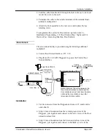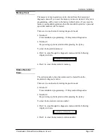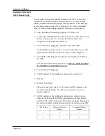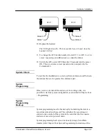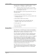
Hardware Installation
Commander i+ Product Service Manual - Issue 2
Page 3-27
•
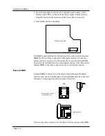
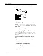
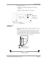
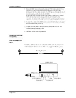
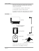
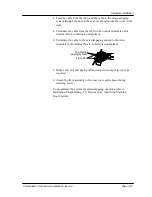
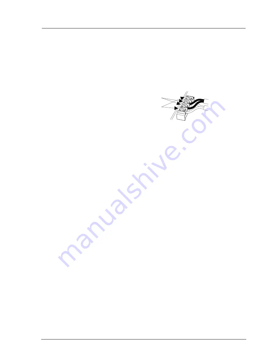
Feed the cable from the AFU and the cable to the external paging
system through the hole in the rear cover and mount the cover to the
wall.
•
Terminate the cable from the AFU to the outside terminals of the
terminal block - polarity is unimportant.
•
Terminate the cable to the external paging system to the inner
terminals of the terminal block - polarity is unimportant.
•
Make a test external paging call and adjust the output level pot as
required.
•
Attach the front assembly to the rear cover and replace the top
retaining screw.
To programme the system for external paging operation refer to
Installation Programming - 13i Devices (Fax, Answering Machine,
Door Station).
To external
paging system
From AFU
Summary of Contents for Commander i
Page 11: ...Chapter One Introduction to the Commander i System ...
Page 19: ...Chapter Two System Description ...
Page 23: ...Chapter Three Hardware Installation ...
Page 24: ......
Page 57: ...Chapter Four Programming ...
Page 83: ......
Page 84: ...Chapter Five Commander Customer Training ...
Page 89: ...Chapter Six Maintenance and Troubleshooting ...
Page 93: ......
Page 94: ...Appendix A Installation Summary ...
Page 102: ...Appendix B Factory Default Values ...
Page 109: ...Appendix D Commander i System User Guide ...
Page 110: ...Telstra Commander i System User Guide Serial Item 749 025 Issue 2 ...
Page 113: ...1 Getting To Know Your Commander i ...
Page 117: ...2 Answering Calls ...
Page 120: ...3 Making Calls ...
Page 123: ...4 Call Handling ...
Page 127: ...5 Other Facilities ...
Page 131: ...6 Programming ...
Page 142: ...Appendix F Commander i AFU User Guide ...
Page 143: ...Telstra Commander i Analogue Facilities Unit User Guide Serial Item 749 35 Issue 2 ...
Page 145: ...1 Introduction ...
Page 148: ...2 How To Use The AFU ...
Page 152: ...3 AFU Quick Reference Card ...

