Hardware Installation
Commander i+ Product Service Manual - Issue 2
Page 3-25
•
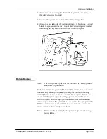
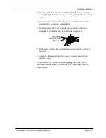
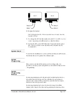
Feed the cable from the AFU through the hole in the rear cover and
mount the cover to the wall.
•
Terminate the cable to the outside terminals of the terminal block -
polarity is unimportant.
•
Attach the front assembly to the rear cover and replace the top
retaining screw.
To programme the system for Door station operation refer to
Installation Programming - 12i Door Station (Day / Night) and 13i
Devices (Fax, Answering Machine, Door Station).
Door Unlock
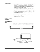
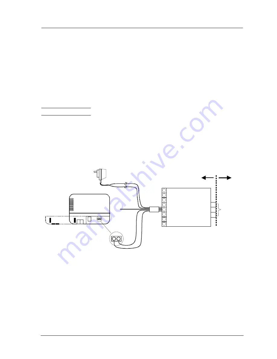
The door unlock facility is provided using the following additional
equipment:
•
Telstra Door Unlock Interface (727 / 29)
•
Plug Pack (749 / 40 AFU Plugpack) to power the Telstra Door
Unlock Interface
Installation
•
Cut the connector from the Plugpack and remove 25 mm from the
outer sheath.
•
Strip 10 mm of insulation from the red and green wires of the
Plugpack , join together and connect to the red (+) wire of the Door
unlock Interface Unit.
•
Strip 10 mm of insulation from the brown and yellow wires of the
Plugpack , join together and connect to the black (-) wire of the
Red
Black
White
Blue
Green
Orange
SD22127
Door Unlock Interface 727 / 29
1
2
3
FRONT VIEW
Sliding Cover
To door unlock
mechanism
Blue 0V
White 5V
Red+
Black -
Orange -
not connected
Green -
not connected
Red / Green
Brown / Yellow
Power Pack 749/40
Telstra
Responsibility
Customer
Responsibility
Safety Warning: The wiring between the
Door Unlock Interface contacts and the
door mechanism must not share the same
cable as the door station or any other
telecommunications wiring.
AFU 749 / 8
Summary of Contents for Commander i
Page 11: ...Chapter One Introduction to the Commander i System ...
Page 19: ...Chapter Two System Description ...
Page 23: ...Chapter Three Hardware Installation ...
Page 24: ......
Page 57: ...Chapter Four Programming ...
Page 83: ......
Page 84: ...Chapter Five Commander Customer Training ...
Page 89: ...Chapter Six Maintenance and Troubleshooting ...
Page 93: ......
Page 94: ...Appendix A Installation Summary ...
Page 102: ...Appendix B Factory Default Values ...
Page 109: ...Appendix D Commander i System User Guide ...
Page 110: ...Telstra Commander i System User Guide Serial Item 749 025 Issue 2 ...
Page 113: ...1 Getting To Know Your Commander i ...
Page 117: ...2 Answering Calls ...
Page 120: ...3 Making Calls ...
Page 123: ...4 Call Handling ...
Page 127: ...5 Other Facilities ...
Page 131: ...6 Programming ...
Page 142: ...Appendix F Commander i AFU User Guide ...
Page 143: ...Telstra Commander i Analogue Facilities Unit User Guide Serial Item 749 35 Issue 2 ...
Page 145: ...1 Introduction ...
Page 148: ...2 How To Use The AFU ...
Page 152: ...3 AFU Quick Reference Card ...

