Hardware Installation
Page 3-10
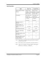
Basic Star Wiring
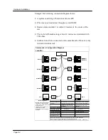
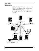
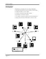
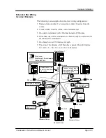
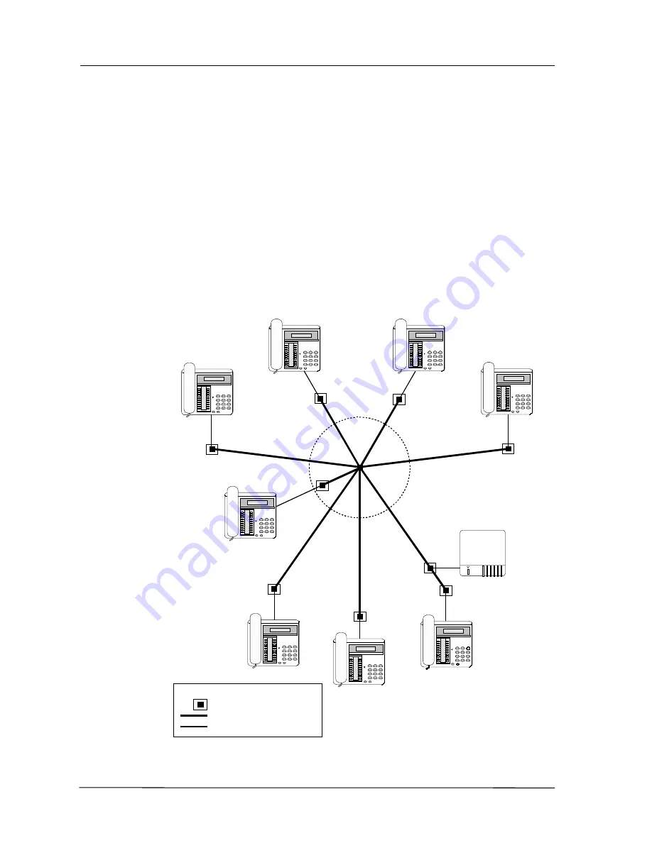
Correct Example
The following is an example of a correct wiring configuration:
•
Each branch longer than 10 metres is terminated with 200 ohms.
•
Number of branches is not more than 8.
•
At least two branches are longer than 10 metres.
•
No branch is over 60 metres in length.
•
Two units are connected on a branch (only end unit terminated).
•
There are less than 4 units within 10 metres of the star centre.
AFU
200 ohms
200 ohms
200 ohm
200 ohms
60 metres
50
m
et
res
40
m
e
tr
es
30
m
etr
es
60 metres
Standard Station
Standard Station
Standard Station
Standard Station
Standard Station
No resistor
Standard Station
200 ohm
No resistor
3 m
Bus Socket
Bus Wiring (0.5 mm diameter)
Station Bus Cord
Legend
Master Station 1
200 ohms
10 metres
Master Station 2
60
m
60
m
200 ohms
Summary of Contents for Commander i
Page 11: ...Chapter One Introduction to the Commander i System ...
Page 19: ...Chapter Two System Description ...
Page 23: ...Chapter Three Hardware Installation ...
Page 24: ......
Page 57: ...Chapter Four Programming ...
Page 83: ......
Page 84: ...Chapter Five Commander Customer Training ...
Page 89: ...Chapter Six Maintenance and Troubleshooting ...
Page 93: ......
Page 94: ...Appendix A Installation Summary ...
Page 102: ...Appendix B Factory Default Values ...
Page 109: ...Appendix D Commander i System User Guide ...
Page 110: ...Telstra Commander i System User Guide Serial Item 749 025 Issue 2 ...
Page 113: ...1 Getting To Know Your Commander i ...
Page 117: ...2 Answering Calls ...
Page 120: ...3 Making Calls ...
Page 123: ...4 Call Handling ...
Page 127: ...5 Other Facilities ...
Page 131: ...6 Programming ...
Page 142: ...Appendix F Commander i AFU User Guide ...
Page 143: ...Telstra Commander i Analogue Facilities Unit User Guide Serial Item 749 35 Issue 2 ...
Page 145: ...1 Introduction ...
Page 148: ...2 How To Use The AFU ...
Page 152: ...3 AFU Quick Reference Card ...

