Hardware Installation
Commander i+ Product Service Manual - Issue 2
Page 3-3
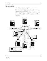
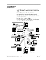
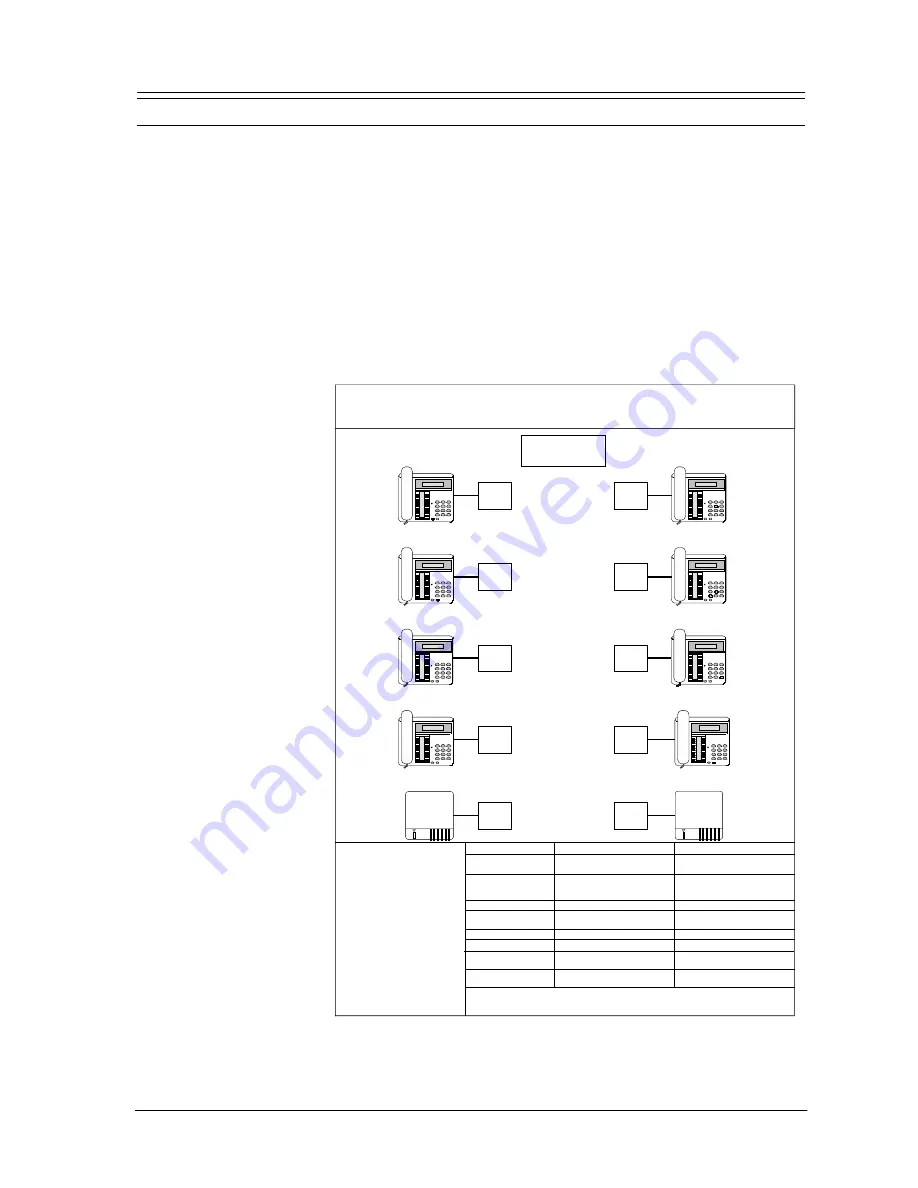
Configuration Diagram
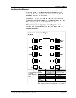
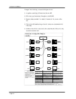
In order to record the configuration used during installation it is
essential to fill in the configuration block diagram showing how the
keystations and AFUs are connected.
Simply draw a line indicating what each unit (keystation / AFU) is
connected to. On the drawn line write in the approximate cable length.
The termination resistor used should also be recorded.
This form is included in Appendix A and can be photocopied as
required. After completing the form it can be left on site with the
system administrator.
Master 1
Standard 3
Standard 5
Standard 7
Standard 8
Master 2 /
Standard 2
Standard 4
Standard 6
MDF
Commander
i
Configuration Diagram
Location:
AFU
AFU
AFU 1
AFU 2
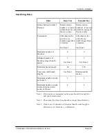
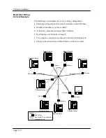
Master station number 1 located
within 60 metres of star centre
200 ohms on the end of every
branch longer than 10 metres
See Note 1
8
2 See Note 2
60
See Note 3
2
4
Master Station Number
1 Position
Termination
Max number of branches
Min number of branches
longer than 10 metres
Max branch length
Total sum of all branches
Max number of units per
branch
Max number of units
within 10 metres of star
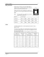
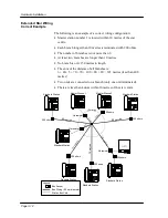
- Maximum bus length: 200 metres.
- Terminations: 100 ohms at ends
of the bus only (2 terminations only).
- No more than four
keystations / AFUs within any 15
metre segment of cable.
- Master stations can be anywhere
on the bus.
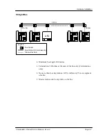
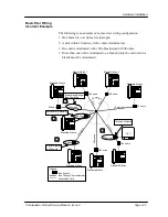
Master station number 1 located
within 10 metres of star centre
200 ohms on the end of every
branch longer than 10 metres
See Note 1
9
2 See Note 2
150
Maximum 400 metres
2
4
Star Wiring Rules
Extended Star
Bus Wiring Rules
Note 1: If two units are connected on a branch then only the end unit is terminated.
Note 2: There must be at least two branches longer than 10 metres
Note 3: If there are 8 branches at 60 metres the total length is 480 m (8 x 60 m = 480 metres)
Basic Star
Summary of Contents for Commander i
Page 11: ...Chapter One Introduction to the Commander i System ...
Page 19: ...Chapter Two System Description ...
Page 23: ...Chapter Three Hardware Installation ...
Page 24: ......
Page 57: ...Chapter Four Programming ...
Page 83: ......
Page 84: ...Chapter Five Commander Customer Training ...
Page 89: ...Chapter Six Maintenance and Troubleshooting ...
Page 93: ......
Page 94: ...Appendix A Installation Summary ...
Page 102: ...Appendix B Factory Default Values ...
Page 109: ...Appendix D Commander i System User Guide ...
Page 110: ...Telstra Commander i System User Guide Serial Item 749 025 Issue 2 ...
Page 113: ...1 Getting To Know Your Commander i ...
Page 117: ...2 Answering Calls ...
Page 120: ...3 Making Calls ...
Page 123: ...4 Call Handling ...
Page 127: ...5 Other Facilities ...
Page 131: ...6 Programming ...
Page 142: ...Appendix F Commander i AFU User Guide ...
Page 143: ...Telstra Commander i Analogue Facilities Unit User Guide Serial Item 749 35 Issue 2 ...
Page 145: ...1 Introduction ...
Page 148: ...2 How To Use The AFU ...
Page 152: ...3 AFU Quick Reference Card ...

