GOT-F900 SERIES (CONNECTION)
Connection of Printer 21
21-5
21
C
o
n
n
e
c
ti
on
of
Pr
in
te
r
22
Co
n
n
e
c
ti
o
n
o
f
Ba
r Co
d
e
R
e
ad
er
23
Ap
p
e
n
d
ix
21.5
Setting of Connected Equipment for GOT
The setting for connection to the printer can be executed using the GOT-F900 and the screen creation
software (GT Designer2, GT Designer or DU/WIN).
1) GOT-F900 Series
When the main menu screen change operation is disabled.
- When the screen data is transferred from screen creation software (GT Designer or DU/WIN) to the GOT-
F900, the old data including the PLC type, connection type, and station number (excluding the printer
status) are overwritten.
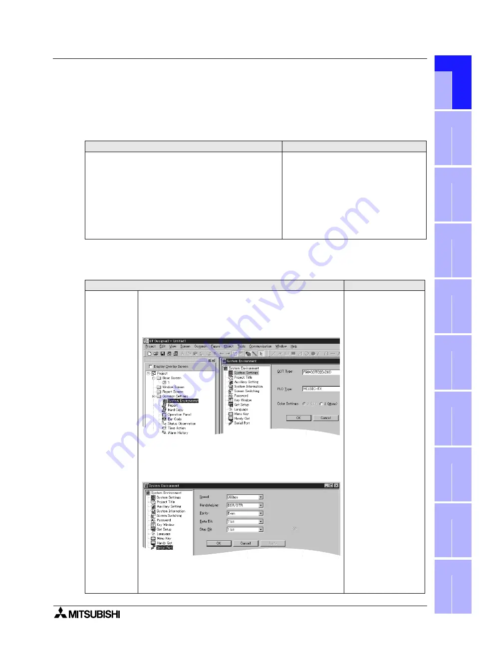
2) GT Designer2
Operation
Display (screen name)
a)While pressing and holding the upper left corner of the screen,
turn on the power. Keep holding the upper left corner for about
25 seconds more.
Then, press "END" at the upper right corner.
The "LANGUAGE" screen appears.
The "SET-UP MODE" screen appears.
b)Press "SERIAL PORT (RS-232C)".
c) Set the transmission specifications for communication with the
printer.
Set "PRINTER" to "DON'T USE".
For the available transmission specifications, refer to section
21.3.
The "SERIAL PORT" screen appears.
Operation
Display (screen name)
[Creation]
a)Open GT Designer2.
b)Read the file of the screen data for which printer connection is to
be set.
c) Set the transmission specifications.
On the menu, select "Common"-"System Environment".
Click "Auxiliary Setting" in the tree of the system environment
menu.
Click the check box of "Use Serial Port, Setup, Language, Menu
Key" to give a check mark (
$
).
Click "Serial Port" in the tree of the system environment menu.
To "Speed", "Hand shaking", etc., set proper contents within the
transmission specifications range for communication with the
printer. After setting, click the [OK] button.
For the available transmission specifications, refer to section 21.3.
The "Project Auxiliary
Settings" dialog box
appears.
Summary of Contents for F920GOT-BBD-K-E
Page 4: ...GOT F900 SERIES CONNECTION ii ...
Page 6: ...GOT F900 SERIES CONNECTION iv ...
Page 38: ...GOT F900 SERIES CONNECTION Outline 2 2 10 MEMO ...
Page 70: ...GOT F900 SERIES CONNECTION Specifications 3 3 32 MEMO ...
Page 230: ...GOT F900 SERIES CONNECTION Connection of MELSEC F FX Series PLC 8 8 26 MEMO ...
Page 260: ...GOT F900 SERIES CONNECTION Connection of MELSEC A Series PLC 9 9 30 MEMO ...
Page 290: ...GOT F900 SERIES CONNECTION Connection of MELSEC QnA Series PLC 10 10 30 MEMO ...
Page 322: ...GOT F900 SERIES CONNECTION Connection of MELSEC Q Series PLC 11 11 32 MEMO ...
Page 376: ...GOT F900 SERIES CONNECTION Connection of FREQROL S500 E500 A500 Inverter 13 13 38 MEMO ...
Page 412: ...GOT F900 SERIES CONNECTION Connection of Microcomputer 14 14 36 MEMO ...
Page 554: ...GOT F900 SERIES CONNECTION Connection of Printer 21 21 8 MEMO ...
Page 590: ...GOT F900 SERIES CONNECTION Appendix 23 23 24 MEMO ...
Page 591: ......


