GOT-F900 SERIES (CONNECTION)
Installation and Wiring of Handy GOT 5
5-51
1
In
tr
o
d
u
c
tio
n
2
Ou
tl
in
e
3
S
p
eci
fic
a
ti
on
s
4
in
st
a
ll
a
ti
o
n
an
d W
iri
ng
o
f
F9
40
G
O
T
5
in
s
ta
llat
io
n
an
d W
ir
in
g
of
Ha
n
d
y
GO
T
6
C
o
nne
c
ti
o
n of
P
e
ri
ph
er
al
Eq
ui
pm
en
t
7
C
o
nn
ect
io
n o
f
T
w
o or
Mor
e
GO
T
U
n
it
s
8
C
o
nn
ec
ti
o
n
of
M
E
LSEC-
F
F
X
Se
ri
e
s
PLC
9
C
o
n
n
e
c
ti
on of
M
E
L
SEC-
A
Se
ri
e
s
PLC
10
C
o
n
n
e
c
ti
on
of
M
E
L
SEC-
Q
n
A
Se
ri
e
s
PLC
3) GT Designer
Operation
Display (screen name)
[Setting]
a)It is supposed that the GT Designer has started up and the screen
data to be set is read.
b)Open a user screen to be set. (Any screen is available as far as it
has been already created.)
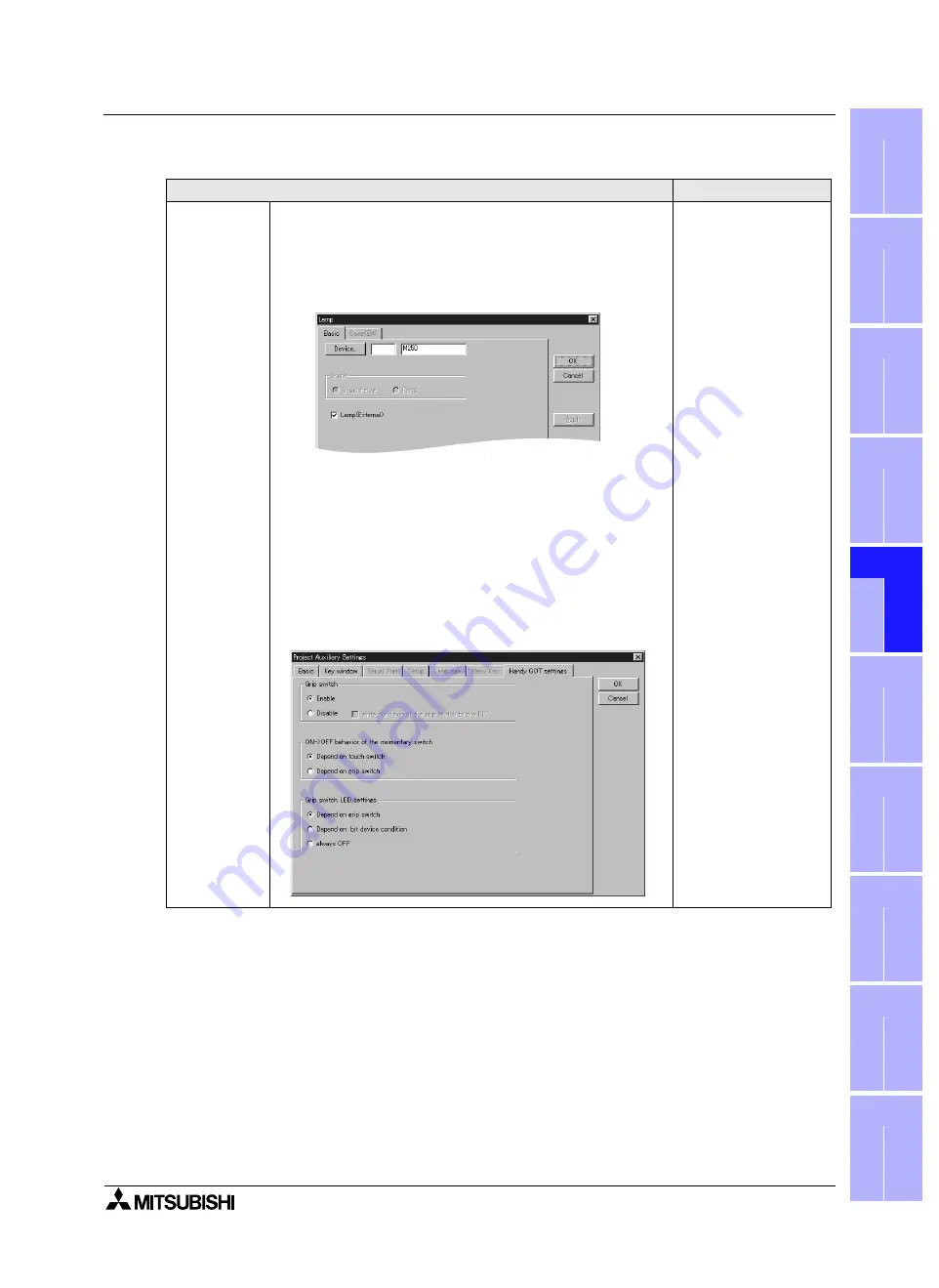
Refer to Caution on setting of "Lamp (External)" below.
[LED setting]
Operation switch
c))Select "Draw"-"Animation Display"-"Lamp" on the menu.
d)On the "Basic" tab, click "Lamp (External)" to give a check mark
(
$
), click the [Device] button, input a bit device to be assigned,
then click [OK].
Refer to Caution on setting of "Lamp (External)" described later.
The "Lamp" dialog box
appears.
[Switch setting]
Grip switch
e)On the menu, select "Common"-"Auxiliary Setting"-"Project".
f) The setting varies depending on the version of the screen creation
software.
<When the GT Designer version is SW5-F (5.05F) or later>
Click the "Handy GOT settings" tab.
When using the grip switch function, set "Enable" to ON. When
not using the grip switch function, set "Disable" to ON.
The "Project Auxiliary
Settings" dialog box
appears.
Summary of Contents for F920GOT-BBD-K-E
Page 4: ...GOT F900 SERIES CONNECTION ii ...
Page 6: ...GOT F900 SERIES CONNECTION iv ...
Page 38: ...GOT F900 SERIES CONNECTION Outline 2 2 10 MEMO ...
Page 70: ...GOT F900 SERIES CONNECTION Specifications 3 3 32 MEMO ...
Page 230: ...GOT F900 SERIES CONNECTION Connection of MELSEC F FX Series PLC 8 8 26 MEMO ...
Page 260: ...GOT F900 SERIES CONNECTION Connection of MELSEC A Series PLC 9 9 30 MEMO ...
Page 290: ...GOT F900 SERIES CONNECTION Connection of MELSEC QnA Series PLC 10 10 30 MEMO ...
Page 322: ...GOT F900 SERIES CONNECTION Connection of MELSEC Q Series PLC 11 11 32 MEMO ...
Page 376: ...GOT F900 SERIES CONNECTION Connection of FREQROL S500 E500 A500 Inverter 13 13 38 MEMO ...
Page 412: ...GOT F900 SERIES CONNECTION Connection of Microcomputer 14 14 36 MEMO ...
Page 554: ...GOT F900 SERIES CONNECTION Connection of Printer 21 21 8 MEMO ...
Page 590: ...GOT F900 SERIES CONNECTION Appendix 23 23 24 MEMO ...
Page 591: ......


