0000
0000
0000
0000
0000
0000
0000
0000
0000
0000
000
000
000
000
000
000
000
000
000
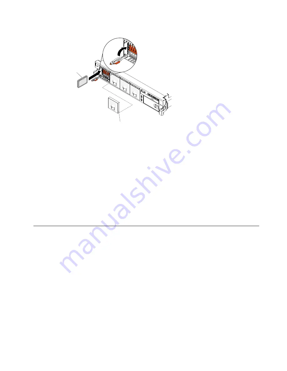
1.8-inch
hot-swap
hard disk drive
Filler
Figure 31. 1.8-inch hot-swap solid state drives installation
c.
Gently push the drive into the bay until the drive stops.
d.
Rotate the handle to the closed (locked) position.
e.
Check the solid state drive status LED to verify that the solid state drive is operating correctly. If
the yellow solid state drive status LED of a drive is lit continuously, that drive is faulty and must
be replaced. If the green solid state drive activity LED is flashing, the drive is being accessed.
Note:
If the server is configured for RAID operation using a ServeRAID adapter, you might
have to reconfigure your disk arrays after you install solid disk drives. See the ServeRAID
adapter documentation for additional information about RAID operation and complete
instructions for using the ServeRAID adapter.
If you have other devices to install or remove, do so now. Otherwise, go to “Completing the installation”
on page 136
Installing an optional DVD drive
Use this information to install an optional DVD drive.
To install an optional DVD drive, complete the following steps:
Step 1.
Read the safety information that begins on “Safety” on page v and “Installation guidelines”
on page 34.
Step 2.
Turn off the server and peripheral devices and disconnect the power cords and all external cables.
Note:
When you disconnect the power source from the server, you lose the ability to view the LEDs
because the LEDs are not lit when the power source is removed. Before you disconnect the
power source, make a note of which LEDs are lit, including the LEDs that are lit on the operation
information panel, on the light path diagnostics panel, and LEDs inside the server on the system
board.
Step 3.
Remove the cover (see “Removing the cover” on page 37).
Step 4.
Remove the DVD drive filler panel if it is installed. Locate the blue release tab on the rear of the DVD
drive filler panel; then, while you press the tab, push the DVD drive filler panel out of the drive bay.
45
Summary of Contents for x3650 M4 BD 5466
Page 1: ...Lenovo System x3650 M4 Installation and Service Guide Machine Type 7915 ...
Page 6: ...iv Lenovo System x3650 M4 Installation and Service Guide ...
Page 176: ...164 Lenovo System x3650 M4 Installation and Service Guide ...
Page 226: ...214 Lenovo System x3650 M4 Installation and Service Guide ...
Page 1042: ...1030 Lenovo System x3650 M4 Installation and Service Guide ...
Page 1200: ...1188 Lenovo System x3650 M4 Installation and Service Guide ...
Page 1204: ...1192 Lenovo System x3650 M4 Installation and Service Guide ...
Page 1212: ...Taiwan BSMI RoHS declaration 1200 Lenovo System x3650 M4 Installation and Service Guide ...
Page 1221: ......
Page 1222: ......


