Chapter 8
List of Data Settings
8-5
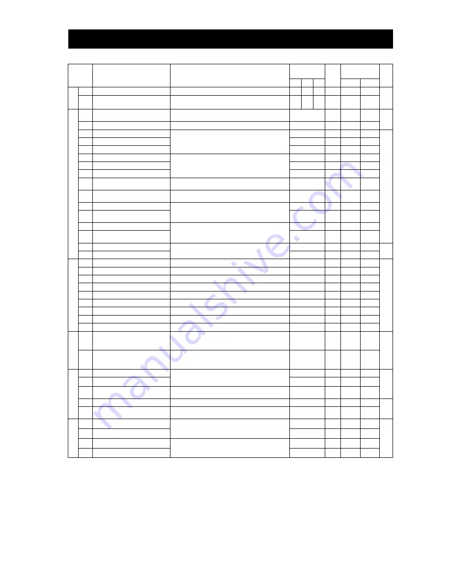
Code
Function name
Monitored data or setting
Default
Memo
Change during
RUN operation
Page
FF
FEF FUF
b031
≠
10 b031=10
A
VR
A081
AVR function select
00 (always on), 01 (always off), 02 (off during deceleration)
02
00
00
Not
Not
4-11
A082
AVR voltage select
200 V class: 200, 215, 220, 230, 240 (V)
400 V class: 380, 400, 415, 440, 460, 480 (V)
200/
400
230/
400
230/
460
Not
Not
O
p
er
at
io
n
m
o
d
e a
n
d
ac
cel
er
at
io
n
/d
ec
el
erat
io
n
f
u
n
ct
io
n
A085
Operation mode selection
00 (normal operation), 01 (energy-saving operation),
02 (fuzzy operation)(only CT)
00
Not
Not
4-32
4-80
A086
Energy saving mode tuning
0.1 to 100.0
50.0
Allowed Allowed
A092
Acceleration (2) time setting
0.01 to 99.99, 100.0 to 999.9, 1000. to 3600. (s)
15.00
Allowed Allowed
4-30
A292
Acceleration (2) time setting, 2nd motor
15.00
Allowed Allowed
A392
Acceleration (2) time setting, 3rd motor
15.00
Allowed Allowed
A093
Deceleration (2) time setting
0.01 to 99.99, 100.0 to 999.9, 1000. to 3600. (s)
15.00
Allowed Allowed
A293
Deceleration (2) time setting, 2nd motor
15.00
Allowed Allowed
A393
Deceleration (2) time setting, 3rd motor
15.00
Allowed Allowed
A094
Select method to switch to Acc2/Dec2
profile
00 (switching by 2CH terminal), 01 (switching by setting),
02 (switching only when rotation is reversed)
00
Not
Not
A294
Select method to switch to Acc2/Dec2, 2nd
motor
00 (switching by 2CH terminal), 01 (switching by setting),
02 (switching only when rotation is reversed)
00
Not
Not
A095
Acc1 to Acc2 frequency transition point
0.00 to 99.99, 100.0 to 400.0 (Hz)
0.00
Not
Not
A295
Acc1 to Acc2 frequency transition point,
2nd motor
0.00
Not
Not
A096
Dec1 to Dec2 frequency transition point
0.00 to 99.99, 100.0 to 400.0 (Hz)
0.00
Not
Not
A296
Dec1 to Dec2 frequency transition point,
2nd motor
0.00
Not
Not
A097
Acceleration curve selection
00 (linear), 01 (S curve), 02 (U curve),
03 (inverted-U curve), 04 (EL-S curve)
00
Not
Not
4-31
A098
Deceleration curve setting
00
Not
Not
Ex
tern
al
f
req
u
en
cy
a
d
ju
st
m
en
t
A101
[OI]-[L] input active range start frequency
0.00 to 99.99, 100.0 to 400.0 (Hz)
0.00
Not
Allowed
4-14
A102
[OI]-[L] input active range end frequency
0.00 to 99.99, 100.0 to 400.0 (Hz)
0.00
Not
Allowed
A103
[OI]-[L] input active range start current
0. to "[OI]-[L] input active range end current" (%)
20.
Not
Allowed
A104
[OI]-[L] input active range end current
"[OI]-[L] input active range start current" to 100. (%)
100.
Not
Allowed
A105
[OI]-[L] input start frequency enable
00 (external start frequency), 01 (0 Hz)
00
Not
Allowed
A111
[O2]-[L] input active range start frequency
-400. to -100., -99.9 to 0.00 to 99.99, 100.0 to 400.0 (Hz)
0.00
Not
Allowed
A112
[O2]-[L] input active range end frequency
-400. to -100., -99.9 to 0.00 to 99.99, 100.0 to 400.0 (Hz)
0.00
Not
Allowed
A113
[O2]-[L] input active range start voltage
-100. to 02 end-frequency rate (%)
-100.
Not
Allowed
A114
[O2]-[L] input active range end voltage
"02 start-frequency rate" to 100. (%)
100.
Not
Allowed
A
cc
el
er
at
io
n
an
d
dec
el
er
ati
o
n
A131
Acceleration curve constants setting
1 (smallest swelling) to 10 (largest swelling)
2
Not
Allowed
4-31
A132
Deceleration curve constants setting
1 (smallest swelling) to 10 (largest swelling)
2
Not
Allowed
O
per
at
io
n
-t
ar
get
fr
equ
enc
y
A141
Operation-target frequency selection 1
00 (digital operator), 01 (keypad potentiometer),
02 (input via O), 03 (input via OI), 04 (external communication),
05 (option 1), 06 (option 2), 07 (pulse-string frequency input)
02
Not
Allowed
4-13
A142
Operation-target frequency selection 2
03
Not
Allowed
A143
Operator selection
00 (addition: A141 + A142), 01 (subtraction: A141 - A142),
02 (multiplication: A141 x A142)
00
Not
Allowed
A145
Frequency to be added
0.00 to 99.99, 100.0 to 400.0 (Hz)
0.00
Not
Allowed
4-14
A146
Sign of the frequency to be added
00 (frequency c A145),
01 (frequency command - A145)
00
Not
Allowed
A
cc
el
er
at
io
n
an
d
dec
el
er
ati
o
n
A150
EL-S-curve acceleration ratio 1
0. to 50. (%)
25.
Not
Not
4-31
A151
EL-S-curve acceleration ratio 2
25.
Not
Not
A152
EL-S-curve deceleration ratio 1
0. to 50. (%)
25.
Not
Not
A153
EL-S-curve deceleration ratio 2
25.
Not
Not
*1 This setting is valid only when the OPE-SR is connected.
(Note) CT : Constant torque mode, VT : Variable torque mode, you can set CT or VT by b049.
Summary of Contents for SJ700D-004L
Page 16: ...Contents Appendix Appendix A 1 Index Index Index 1 ...
Page 44: ...Chapter 2 Installation and Wiring 2 23 Memo ...
Page 70: ...Chapter 3 Operation 3 25 Memo ...
Page 248: ...Chapter 5 Error Codes 5 11 Memo ...
Page 256: ...Chapter6 Maintenance and Inspection 6 7 Memo ...


