Chapter 4
Explanation of Functions
4-102
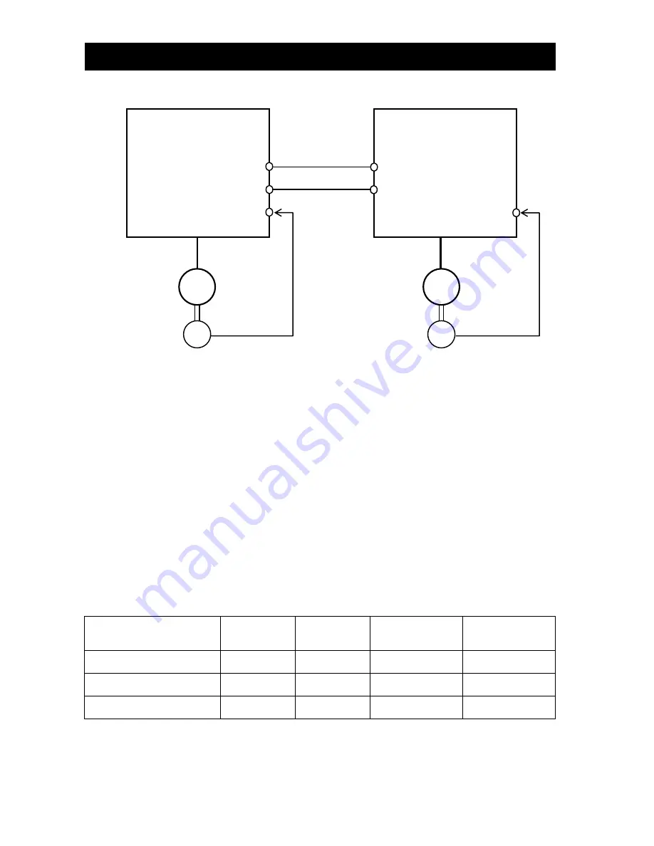
<Example of use: Synchronous operation>
On the inverter (master inverter) for the main motor, specify either the speed control (ASR:P012=00) or pulse train
position control mode (APR:P012=01).
On the inverter (slave inverter) for the sub-motor, specify the pulse train position control mode (APR:P012=01). And
set the frequency source setting(A001) selection to the pulse row input”06”. Please set the pulse train position
command input enable signal(STAT) to an unused input terminal. Afterwards, put the intelligent input terminal into
the state of turning on.
<Example of settings>
- Main motor: Encoder pulse-per-revolution (PPR) setting = 1024 (pulses)
- Sub-motor: Encoder pulse-per-revolution (PPR) setting = 3000 (pulses)
- Ratio of main motor speed to sub-motor speed: 2:1
To operate the motors under the above conditions, adjust the parameters on the slave inverter as follows:
Pulse train mode setting (P013): 00 (90º-phase-shift pulse train)
Electronic gear set position selection (P019): 01 (REF)
Electronic gear ratio numerator setting (P020): 3000
Electronic gear ratio denominator setting (P021): 1024 x 2 = 2048
The table below lists the Examples of the ratio of main motor speed to sub-motor speed according to the settings of
"P019" to "P021" (on the assumption that the encoder pulse-per-revolution (PPR) setting of "1024" should be set on
both inverters).
Electronic gear set position
selection (P019)
REF
(Position
command side)
REF
(Position
command side)
FB
(Position feedback
side)
FB
(Position feedback
side)
Electronic gear ratio numerator
setting (P020)
1024
2048
1024
2048
Electronic gear ratio denominator
setting (P021)
2048
1024
2048
1024
Sub-motor speed/main motor
speed
1/2
2
2
1/2
-Please confirm the instruction value in which the rotational speed corresponds between while the mastering inverter
is driven is displayed in the output frequency setting(F001) on the slave side when the driving instruction is put, and
the slave side doesn't drive.
-Please raise and adjust the feed-forward gain setting(P022) or the positional loop gain setting(P023) when the
response of the follow on the slave side is late. (Refer to Chapter 4.3.7 )
AP,BP
AN,BN
M
EC
M
EC
EG5
EAP,EBP
EAN,EBN
SAP,SBP
SAN,SBN
EG5
EAP,EBP
EAN,EBN
Master inverter
Slave inverter
Main motor
Sub-motor
Summary of Contents for SJ700D-004L
Page 16: ...Contents Appendix Appendix A 1 Index Index Index 1 ...
Page 44: ...Chapter 2 Installation and Wiring 2 23 Memo ...
Page 70: ...Chapter 3 Operation 3 25 Memo ...
Page 248: ...Chapter 5 Error Codes 5 11 Memo ...
Page 256: ...Chapter6 Maintenance and Inspection 6 7 Memo ...


