1. Operational Overview
1-4
Radar display
The radar is initially set to previously used range and pulse length. Other settings such as brilliance levels, VRMs,
EBLs and menu option selections are also set to previous settings.
The
STBY/TX
key (or TX STBY box) toggles the radar between STBY and TRANSMIT state. The antenna stops
in stand-by and rotates in transmit. The magnetron ages with time resulting in a reduction of output power.
Therefore, it is highly recommended that the radar be set to stand-by when not used for an extended period of time.
Picture freeze
If the picture freezes the picture is not updated. 30 seconds after the picture freezes, the buzzer sounds, the [ALARM
ACK] key blinks and alarm contact signal is output. Reset the power to restore normal operation.
How to stop antenna rotation
Antenna rotation can be stopped. One method is to turn off the antenna switch on the radar. The other method is to
stop rotation from the menu. For how to stop rotation from the menu, see the installation manual.
About on-screen boxes and indications
The on-screen boxes, like the TX STBY box, provide for adjustment of the item which appears on their labels. Some
indications also function to provide adjustment of a specific function. When you put the cursor inside a box or on an
indication, the color of the label in the box or the indication changes (example: yellow to green). This indicates that
the box or indication is correctly selected. Then, you can change setting by pushing the left button.
1.3 Monitor
Brilliance
The brilliance of the entire screen should be adjusted according to lighting conditions. Monitor brilliance should be
adjusted before adjusting relative brilliance levels on the BRILL menu.
Note:
The brilliance of a commercial monitor cannot be adjusted from the radar. See the owner’s manual of the
commercial monitor for how to adjust its brilliance.
Adjusting brilliance with the keyboard-equipped control unit
Operate the
BRILL
control to adjust brilliance. Turn it clockwise to increase brilliance; counterclockwise to
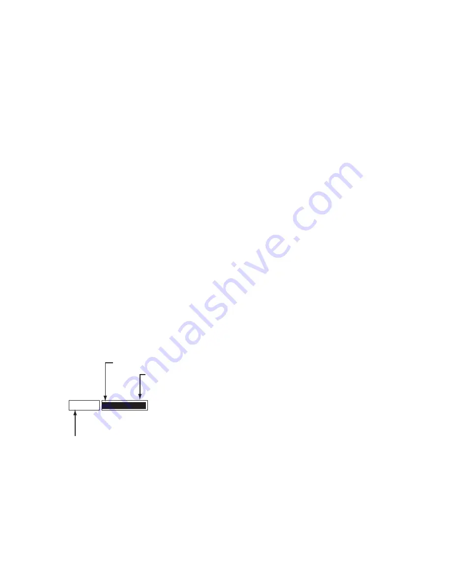
decrease brilliance. Watch the BRILL box (see illustration below) to know current brilliance level.
Adjusting brilliance with the trackball
1. Use the trackball to place the arrow on the brilliance level indicator in the BRILL box at the bottom left corner of
the screen.
Brilliance level
Put arrow inside box to
adjust screen brilliance.
Brilliance color set no.
BRILL 1
16/16
BRILL box
2. Spin the scrollwheel downward to increase brilliance or spin it upward to decrease brilliance. The length of the
brilliance bar increases or decreases with operation of the scrollwheel.
Note:
If nothing appears on the screen at power-up when using Control Unit RCU-015 (palm control) or when the
radar is in stand-by, push and hold down any key except the power switch for four seconds to automatically set up
for medium display brilliance.
Summary of Contents for FCR-2107 series
Page 42: ...1 Operational Overview 1 20 This page intentionally left blank...
Page 154: ...5 AIS Operation 5 28 This page intentionally left blank...
Page 255: ...7 Vector Chart Material 7 83 Recommended track defined by two beacons...
Page 256: ...7 Vector Chart Material 7 84 Recommended track defined by a building and a beacon...
Page 257: ...7 Vector Chart Material 7 85 Measurement mile tails tails...
Page 298: ...9 Chart Alerts 9 14 This page intentionally left blank...
Page 322: ...10 Route Planning 10 24 This page intentionally left blank...
Page 368: ...14 Backup Operations 14 6 This page intentionally left blank...
Page 404: ...16 Recording Functions 16 16 This page intentionally left blank...
Page 406: ...17 NAVTEX Messages 17 2 This page intentionally left blank...
Page 416: ...19 Parameters Setup 19 8 This page intentionally left blank...
Page 457: ...Appendix 2 IHO ECDIS Chart 1 AP 5 Nature and Man made features Port features...
Page 458: ...Appendix 2 IHO ECDIS Chart 1 AP 6 Depths Currents etc Seabed Obstructions Pipelines etc...
Page 459: ...Appendix 2 IHO ECDIS Chart 1 AP 7 Traffic routes Special areas...
Page 460: ...Appendix 2 IHO ECDIS Chart 1 AP 8 Aids and Services Buoys and Beacons...
Page 461: ...Appendix 2 IHO ECDIS Chart 1 AP 9 Topmarks Color test diagram...
Page 462: ...Appendix 2 IHO ECDIS Chart 1 AP 10 Mariners navigational symbols...
Page 469: ...Appendix 3 Interpreting S57 Charts AP 17 Fog signals Radars Services...
Page 476: ...Appendix 3 Interpreting S57 Charts AP 24 This page intentionally left blank...
Page 511: ...Appendix 5 Digital Interface AP 59 NRX NAVTEX received data...
Page 544: ...Appendix 6 Parts List and Parts Location AP 92 This page intentionally left blank...
Page 550: ...This page is intentionally left blank...
Page 556: ......


