4. Tracked Target (TT) Operation
4-19
4.14 Setting an Acquisition Zone
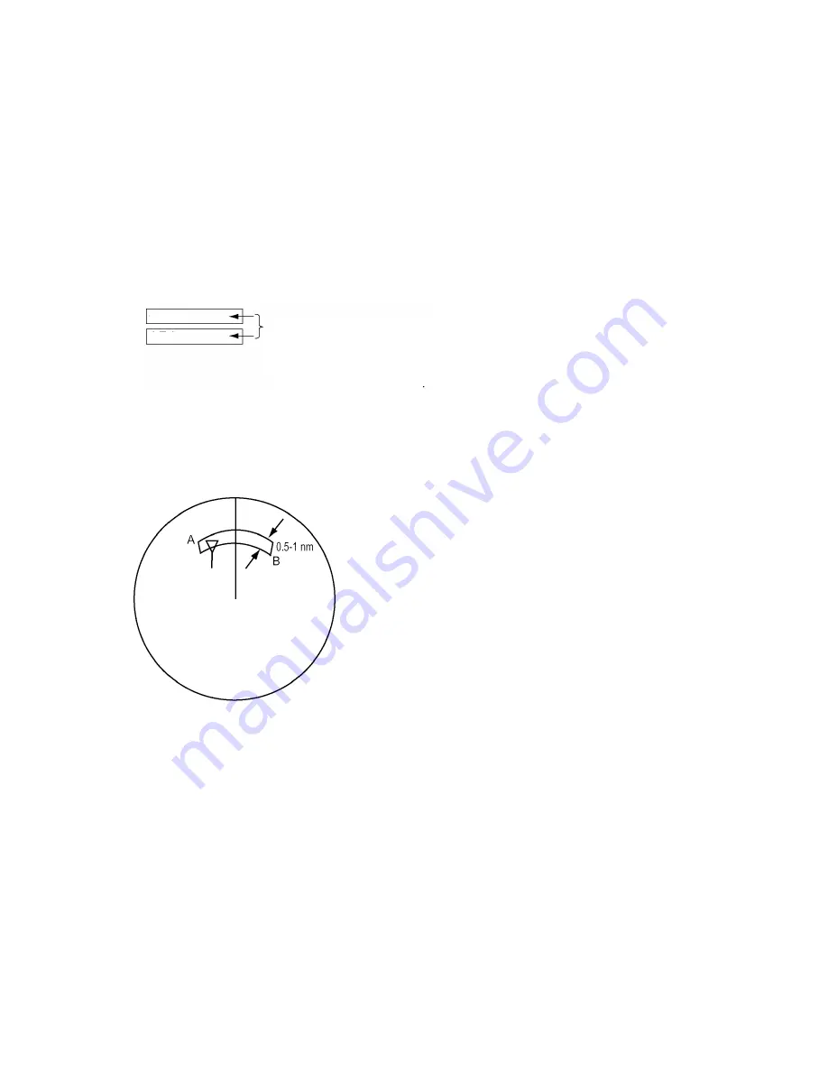
The acquisition zone functions both to alert you targets in a specific area and acts as an automatic acquisition area
when automatic target acquisition is active. Any targets entering the zone will be automatically acquired.
When a target enters an acquisition zone, the buzzer sounds and the indication TT target in ACQ ZONE (or AIS
target in ACQ ZONE) appears (in yellow) in the Alert Box. The symbol of the offending target is red and flashing.
Further, the AIS display is automatically turned on if it is off.
4.14.1 Activating an acquisition zone
One or two acquisition zones may be set, and the maximum range for AZ1 is 6 nm and 24 nm for AZ2.
The procedure below shows how to set an acquisition zone, using the example at the bottom of the page.
1. Use the trackball to select GZ1 box at the right side of the screen.
AZ1
AZ2
AZ status:
Blank:
AZ off
SET:
Set AZ
WORK: AZ active
SLEEP: AZ "asleep
AZ boxes
2. Push the left button. The AZ box now reads "As SET."
3. Use the trackball to place the cursor on point A then push the left button.
4. Use the trackball to place the cursor on point B then push the left button.
The GZ box now reads "As WORK."
Target in acquisition
zone is marked with
an inverted triangle.
Acquisition zone
Note 1:
If you wish to create an acquisition zone having a 360-degree coverage around own ship, set point B in
almost the same direction (approx. ±3°) as point A then push the left button.
Note 2:
If the range scale is changed to less than half of the acquisition zone, the AZ box reads "As OUT." If the left
button is pushed in this state, the acquisition alarm zone goes into "sleep" state (inactive) and the guidance area
reads "AZ WORK L = DELETE."
Summary of Contents for FCR-2107 series
Page 42: ...1 Operational Overview 1 20 This page intentionally left blank...
Page 154: ...5 AIS Operation 5 28 This page intentionally left blank...
Page 255: ...7 Vector Chart Material 7 83 Recommended track defined by two beacons...
Page 256: ...7 Vector Chart Material 7 84 Recommended track defined by a building and a beacon...
Page 257: ...7 Vector Chart Material 7 85 Measurement mile tails tails...
Page 298: ...9 Chart Alerts 9 14 This page intentionally left blank...
Page 322: ...10 Route Planning 10 24 This page intentionally left blank...
Page 368: ...14 Backup Operations 14 6 This page intentionally left blank...
Page 404: ...16 Recording Functions 16 16 This page intentionally left blank...
Page 406: ...17 NAVTEX Messages 17 2 This page intentionally left blank...
Page 416: ...19 Parameters Setup 19 8 This page intentionally left blank...
Page 457: ...Appendix 2 IHO ECDIS Chart 1 AP 5 Nature and Man made features Port features...
Page 458: ...Appendix 2 IHO ECDIS Chart 1 AP 6 Depths Currents etc Seabed Obstructions Pipelines etc...
Page 459: ...Appendix 2 IHO ECDIS Chart 1 AP 7 Traffic routes Special areas...
Page 460: ...Appendix 2 IHO ECDIS Chart 1 AP 8 Aids and Services Buoys and Beacons...
Page 461: ...Appendix 2 IHO ECDIS Chart 1 AP 9 Topmarks Color test diagram...
Page 462: ...Appendix 2 IHO ECDIS Chart 1 AP 10 Mariners navigational symbols...
Page 469: ...Appendix 3 Interpreting S57 Charts AP 17 Fog signals Radars Services...
Page 476: ...Appendix 3 Interpreting S57 Charts AP 24 This page intentionally left blank...
Page 511: ...Appendix 5 Digital Interface AP 59 NRX NAVTEX received data...
Page 544: ...Appendix 6 Parts List and Parts Location AP 92 This page intentionally left blank...
Page 550: ...This page is intentionally left blank...
Page 556: ......


