9. Chart Alerts
9-10
9.4 Route
Planning
The system will calculate chart alerts using user-defined channel limit for routes. Danger areas are shown
highlighted if safety contour or user-chosen chart alert areas are crossed by the planned route. For more information
on route planning, see Chapter 10 Route Planning.
Note:
If your voyage is going to take a long time or you are planning it much earlier than it is to take place, use
display and approve dates corresponding to the dates you are going to sail.
Chart alerts for route planning
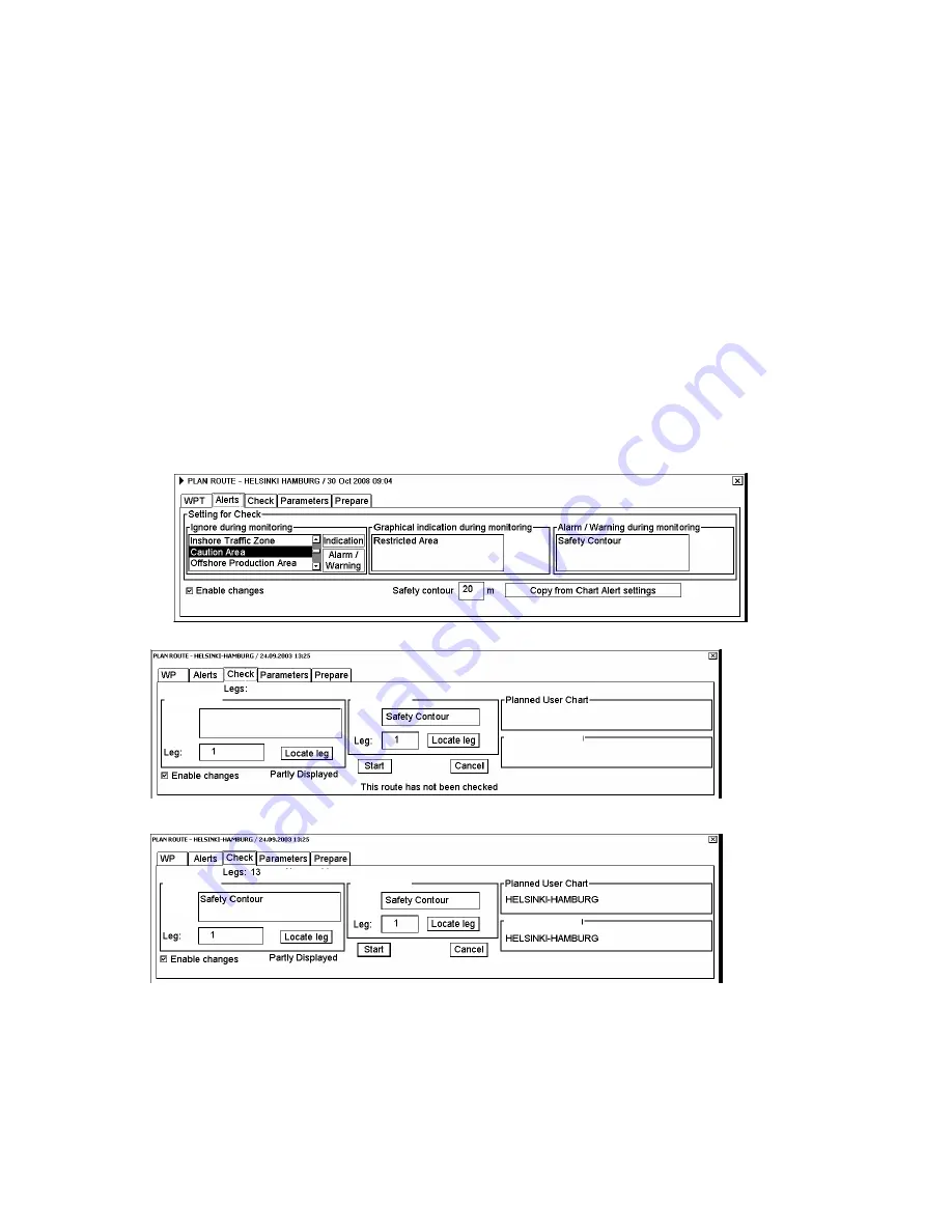
You can generate a list of chart alerts which cross by the planned route. This can be done as follows:
1. Enter safety contour you want to use. See section 9.1.1 Choosing safety contour.
2. Plan a route; define waypoints and other necessary information. See Chapter 10 Route Planning.
3. Choose dangerous objects to be monitored during route monitoring, on the Alerts page in the Plan Route dialog
box, shown below.
a) Open the Plan Route dialog box by selecting User Chart-Plan from the status bar.
b) Click the Alerts tab.
c) Check the Enable changes box, then click the alert to process from the Ignore during monitoring list then
click the
Indication
or
Alarm/Warning
button as appropriate to choose what type of alert you want.
4. Click the Check tab then click the
Start
button to generate a list of chart alerts.
Alerts:
Alerts by leg
Legs by alert
Alert:
Alerts:
Planned Notes
The system will check a route leg by leg and when finished you will see the number of Legs and Alerts
below
the tab buttons.
Alerts by leg
Legs by alert
Alerts: 11
Legs by alert
Alerts by leg
Alert:
Alerts:
Planned Notes
The figure above shows the alerts to be monitored. If there are alerts included in the planned route, check alerts
leg by leg, or check alerts by using category of alert.
Summary of Contents for FCR-2107 series
Page 42: ...1 Operational Overview 1 20 This page intentionally left blank...
Page 154: ...5 AIS Operation 5 28 This page intentionally left blank...
Page 255: ...7 Vector Chart Material 7 83 Recommended track defined by two beacons...
Page 256: ...7 Vector Chart Material 7 84 Recommended track defined by a building and a beacon...
Page 257: ...7 Vector Chart Material 7 85 Measurement mile tails tails...
Page 298: ...9 Chart Alerts 9 14 This page intentionally left blank...
Page 322: ...10 Route Planning 10 24 This page intentionally left blank...
Page 368: ...14 Backup Operations 14 6 This page intentionally left blank...
Page 404: ...16 Recording Functions 16 16 This page intentionally left blank...
Page 406: ...17 NAVTEX Messages 17 2 This page intentionally left blank...
Page 416: ...19 Parameters Setup 19 8 This page intentionally left blank...
Page 457: ...Appendix 2 IHO ECDIS Chart 1 AP 5 Nature and Man made features Port features...
Page 458: ...Appendix 2 IHO ECDIS Chart 1 AP 6 Depths Currents etc Seabed Obstructions Pipelines etc...
Page 459: ...Appendix 2 IHO ECDIS Chart 1 AP 7 Traffic routes Special areas...
Page 460: ...Appendix 2 IHO ECDIS Chart 1 AP 8 Aids and Services Buoys and Beacons...
Page 461: ...Appendix 2 IHO ECDIS Chart 1 AP 9 Topmarks Color test diagram...
Page 462: ...Appendix 2 IHO ECDIS Chart 1 AP 10 Mariners navigational symbols...
Page 469: ...Appendix 3 Interpreting S57 Charts AP 17 Fog signals Radars Services...
Page 476: ...Appendix 3 Interpreting S57 Charts AP 24 This page intentionally left blank...
Page 511: ...Appendix 5 Digital Interface AP 59 NRX NAVTEX received data...
Page 544: ...Appendix 6 Parts List and Parts Location AP 92 This page intentionally left blank...
Page 550: ...This page is intentionally left blank...
Page 556: ......


