100/180 mm PAPERLESS GRAPHIC RECORDER: USER GUIDE
User Guide
Page 159
HA028910
Issue 13 Sep 16
4.3.16 MASTER COMMS (Cont.)
SHARE SOCKET
This advanced confi guration feature is used to improve communications performance, to take advantage
of the higher speed of Ethernet links compared with ‘Serial’ links. It is recommended that the default
value (enabled or disabled according to type) be left as despatched from the factory, unless there is
good reason to change it.
A socket is the name given to a logical connection between two Ethernet nodes. The establishment and
maintenance of sockets is controlled by the recorder, and the user has no control other than to enable
or disable the ‘Share sockets’ facility. The share socket feature is available only for slaves confi gured as
Ethernet devices (i.e. Network = Ethernet).
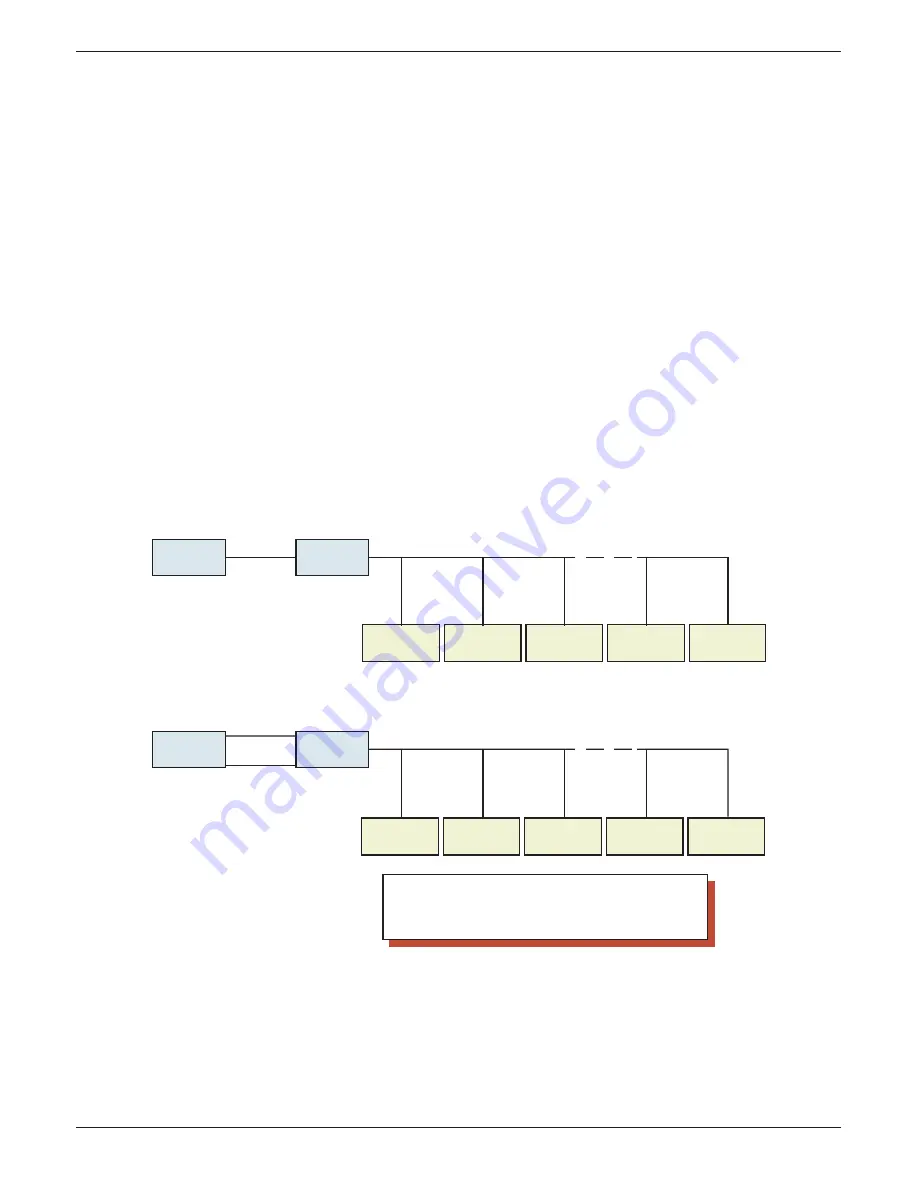
The upper illustration in fi gure 4.3.16d, shows master 1 communicating with slaves 1 to n via an Ethernet-
to-Serial converter, called a Modbus Gateway. In such a case, it is more effi cient to allow all the slaves to
communicate over one link between master 1 and master 2, than to establish individual links between
master 1 and each of the slaves. In this example, ‘Share sockets’ should be enabled.
The lower illustration show a similar situation, except that master 2 is not just a gateway, but is a meas-
uring device in its own right. In such a case, Socket 1 is used for high speed communications between
master 1 and master 2, and Socket 2 is used to link master 1 to the slaves individually. In this case ‘Share
Sockets’ should be disabled for master 2, and enabled for all other devices.
Figure 4.3.16d Share socket examples
Slave 1
IP:123.123.1.2
Modbus Address 1
Slave 2
IP:123.123.1.2
Modbus Address 2
Slave 3
IP:123.123.1.2
Modbus Address 3
Slave n-1
IP:123.123.1.2
Modbus Addr. n-1
Slave n
IP:123.123.1.2
Modbus Address n
Master 1
Ethernet
IP address:
123.123.1.2
Modbus address: 10
Master 2
(TCP-Gateway)
Serial link (RS485)
Notes:
1. The IP address '123.123.1.2' is for demonstration purposes only
2. Modbus address can be any number between 1 and 247, but must be
unique per IP address.
3. Modbus addresses need not be consecutive
Master 1
Socket 1
IP address:
123.123.1.2
Modbus address: 10
Master 2
(Instrument)
Serial link (RS485)
Socket 2
Socket 1 Communicates with IP address
123. 123.1.2, Modbus address 10.
Socket 2 communicates with IP Address
123.123.1.2, Modbus addresses 1 to n
Ethernet
Socket 1
Socket 1 communicates with IP Address
123.123.1.2, Modbus addresses 1 to n
Slave 1
IP:123.123.1.2
Modbus Address 1
Slave 2
IP:123.123.1.2
Modbus Address 2
Slave 3
IP:123.123.1.2
Modbus Address 3
Slave n-1
IP:123.123.1.2
Modbus Addr. n-1
Slave n
IP:123.123.1.2
Modbus Address n


