3. OPERATION AND TIMING
COPYRIGHT © 2001 CANON INC. CANON CLC1000/1000S/3100 REV.2 MAY 2001 PRINTED IN JAPAN (IMPRIME AU JAPON)
3-66
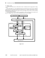
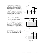
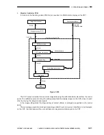
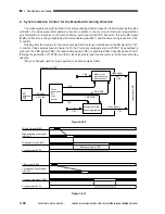
D. Generating the BD Signal
The BD signal is used to synchronize video signals (for the main scanning direction of the laser beam).
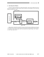
The laser beam reflected by the BD mirror located in the optical path of the beam is detected by the BD
detection PCB, and the detection signal is used to generate the BD signal. As can be learned from Figure 3-
406, as many as four BD detection PCBs are used to deal with the four colors and the BD signal is generated
for each channel.
Figure 3-406
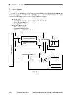
In reference to the BD signal for each color, the video signal is synchronized for the main scanning
direction on the video controller PCB (details follow) and sent to the laser driver PCB.
Figure 3-407
Bk drum
C drum
M drum
Y drum
Feeding direction
Bk BD detection PCB
C BD detection PCB
M BD detection PCB
Y BD detection PCB
Video controller PCB
BD signal
BD signal
Y,M,C,Bk
Y,M
Y,M
C,K
C,K
Main scanning
synchronization
Main scanning
synchronization
Video signal
Video signal
Video signal
BD signal
Y,M,C,K
Video controller PCB
BD detection
PCB
Image processor PCB
Laser driver PCB
Summary of Contents for Vizcam 1000
Page 12: ......
Page 30: ......
Page 44: ......
Page 86: ......
Page 254: ......
Page 372: ......
Page 374: ......
Page 418: ......
Page 438: ......
Page 442: ......
Page 754: ......
Page 764: ......
Page 766: ......
Page 840: ...0501GR PRINTED IN JAPAN IMPRIME AU JAPON This publication is printed on 100 reprocessed paper...

