COPYRIGHT © 2001 CANON INC. CANON CLC1000/1000S/3100 REV.2 MAY 2001 PRINTED IN JAPAN (IMPRIME AU JAPON)
I.
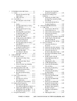
EXTERNALS AND CONTROLS .............. 4-1
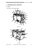
A. Covers ............................................... 4-1
1. External Covers and Copy
board Glass ................................ 4-1
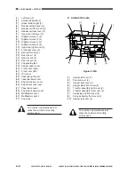
2. Internal Covers ........................... 4-2
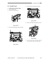
B. Control Panel ...................................... 4-3
1. Removing the Control Panel ........ 4-3
C. Fans ................................................... 4-4
1. Outline ........................................ 4-4
2. Removing the Delivery Cooling
Fan (FM1/2/3) ............................. 4-4
3. Removing the Laser Cooling
Fan (FM4/5) ................................ 4-4
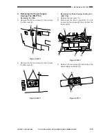
4. Removing the Power Supply
Cooling Fan (FM17/18) ................ 4-5
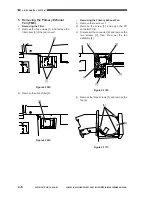
5. Removing the Primary
Exhaust Fan (FM6) ..................... 4-6
6. Primary Suction Fan (FM8/9) ..... 4-7
7. Removing the Scanner
Suction Fan (FM12/13) ............... 4-7
8. Removing the Scanner Cooling
Fan (FM10/11) ............................. 4-8
9. Removing the Digital Unit
Cooling Fan (FM14/15/16) .......... 4-8
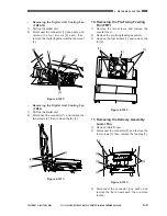
10. Removing the Pre-Fixing
Feeding Fan (FM7) ..................... 4-9
11. Removing the Delivery
Assembly Lower Fan .................. 4-9
II.
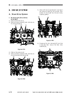
DRIVE SYSTEM .................................... 4-10
A. Drum Drive System ......................... 4-10
1. Removing the Drum Drive
Assembly .................................. 4-10
2. Removing the Drum Motor
Assembly .................................. 4-11
3. Points to Note When Installing
the Drum Drive Belt .................. 4-11
B. Developing Motor Assembly ............ 4-11
1. Removing the Developing
Motor Assembly ........................ 4-11
2. Removing the Developing
Motor ........................................ 4-12
C. Pick-Up Drive Assembly .................. 4-12
1. Outline ...................................... 4-12
2. Removing the Pick-Up
Drive Assembly ........................ 4-13
3. Removing the Pick-Up Motor ... 4-14
D. Scanner Drive Assembly ................. 4-15
1. Removing the Scanner
Drive Assembly/Scanner Motor 4-15
2. Adjusting the Belt Tension When
Installing the Scanner Motor ..... 4-15
3. Routing the Scanner Cable ...... 4-15
E. Fixing Drive Assembly ..................... 4-18
1. Removing the Fixing Drive
Assembly/Fixing Motor ............. 4-18
F.
Waste Toner Feeding Drive
Assembly ......................................... 4-19
1. Removing the Waste Toner
Feeding Drive Assembly/Waste
Toner Motor .............................. 4-19
2. Removing the Waste Toner
Feeding Pipe/Screw .................. 4-20
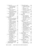
III.
PICK-UP/FEEDING SYSTEM ............... 4-21
A. Paper Deck ...................................... 4-21
1. Removing the Paper Deck ........ 4-21
2. Removing the Cover ................. 4-21
3. Removing the Pick-Up Roller .... 4-22
4. Removing the Pick-Up/
Feeding Roller .......................... 4-22
5. Removing the Separation Roller4-24
6. Positioning the Pick-Up Roller
Releasing Solenoid .................. 4-26
7. Adjusting the Paper Surface ..... 4-26
B. Pick-Up Assembly ........................... 4-27
1. Removing the Pick-Up
Assembly .................................. 4-27
2. Removing the Pick-Up Roller ... 4-27
3. Removing the Feeding Roller ... 4-28
4. Removing the Pick-Up
Assembly Separation Roller ..... 4-29
5. Adjusting the Separation Roller
Pressure ................................... 4-30
6. Positioning the Pick-Up
RollerReleasing Solenoid
(SL9, SL10) .............................. 4-31
7. Releasing the Lifter .................. 4-31
8. Left/Right Registration .............. 4-31
9. Removing the Duplexing
Pick-Up Roller .......................... 4-32
10. Removing the Duplexing
Feeding Roller 1 ....................... 4-33
11. Removing the Duplexing
Feeding Roller 2 ....................... 4-33
C. Multifeeder Assembly ...................... 4-35
1. Removing the Multifeeder
Tray Assembly .......................... 4-35
2. Removing the Multifeeder
Assembly .................................. 4-35
3. Removing the Multifeeder
Assembly Pick-Up Roller .......... 4-35
4. Removing the Multifeeder
Assembly Feeding Roller/
Separation Roller ...................... 4-36
5. Adjusting the Separation
Roller ........................................ 4-36
6. Releasing the Lifter .................. 4-37
COPYRIGHT © 2001 CANON INC. CANON CLC1000/1000S/3100 REV.2 MAY 2001 PRINTED IN JAPAN (IMPRIME AU JAPON)
Summary of Contents for Vizcam 1000
Page 12: ......
Page 30: ......
Page 44: ......
Page 86: ......
Page 254: ......
Page 372: ......
Page 374: ......
Page 418: ......
Page 438: ......
Page 442: ......
Page 754: ......
Page 764: ......
Page 766: ......
Page 840: ...0501GR PRINTED IN JAPAN IMPRIME AU JAPON This publication is printed on 100 reprocessed paper...

