7-113
COPYRIGHT © 2001 CANON INC. CANON CLC1000/1000S/3100 REV.2 MAY 2001 PRINTED IN JAPAN (IMPRIME AU JAPON)
7. TROUBLESHOOTING IMAGE FAULTS/MALFUNCTIONS
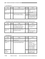
21
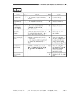
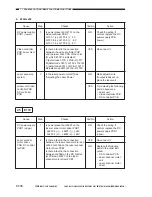
E073
22
E074
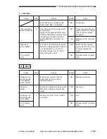
Cause
Transfer belt
lifter sensor 1
(PS12), 2 (PS13)
Operation
(faulty)
Sensor (position)
Pick-up motor
Transfer belt
lifter clutch
(CL17)
DC controller
PCB
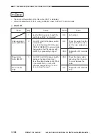
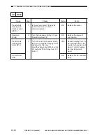
Cause
Transfer frame
drawer connec-
tor, DC controller
PCB
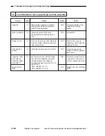
Step
1
Checks
Is the transfer frame drawer connec-
tor soiled with toner or damaged?
Yes/No
YES
NO
Action
Clean and replace the
drawer connector.
Check the wiring from
J2218 on the DC control-
ler PCB to the transfer
frame drawer connector
J6122; if normal, replace
the DC controller PCB.
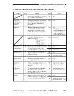
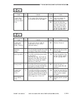
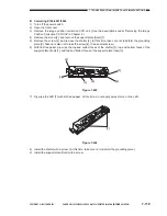
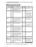
Step
1
2
3
4
5
Checks
Is the sensor normal? (See the
instructions on how to check
photointerrupters.)
Turn the transfer belt lifter drive shaft
by a finger. Does it turn smoothly?
Turn OFF and ON the power switch
to clear ‘E074’.
Press the Start key, and check the
operation of the lifter of the transfer
belt by the eye. Does the transfer
belt move up and down?
Turn OFF and ON the power switch
once again, and press the Start key.
Does the pick-up motor rotate?
Turn OFF and ON the power switch
once again, and press the Start key.
Does the voltage between J2226A-5
and J2226A-4 on the DC controller
PCB change from 0 V to 24 V?
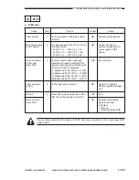
Yes/No
NO
NO
YES
NO
YES
NO
Action
Replace the sensor.
Remove the cause of the
faulty rotation.
Check the position of the
sensor; if normal, replace
the DC controller PCB.
Check the wiring; if
normal, replace the pick-
up motor.
Check the wiring from the
clutch to the DC controller
PCB; if normal, replace
the clutch.
Replace the DC controller
PCB.
Summary of Contents for Vizcam 1000
Page 12: ......
Page 30: ......
Page 44: ......
Page 86: ......
Page 254: ......
Page 372: ......
Page 374: ......
Page 418: ......
Page 438: ......
Page 442: ......
Page 754: ......
Page 764: ......
Page 766: ......
Page 840: ...0501GR PRINTED IN JAPAN IMPRIME AU JAPON This publication is printed on 100 reprocessed paper...


