background image

7-52

COPYRIGHT © 2001 CANON INC.               CANON CLC1000/1000S/3100 REV.2 MAY 2001 PRINTED IN JAPAN (IMPRIME AU JAPON)

7. TROUBLESHOOTING IMAGE FAULTS/MALFUNCTIONS

III. TROUBLESHOOTING IMAGE PROBLEMS

4. Checking the Charging Assem-

blies

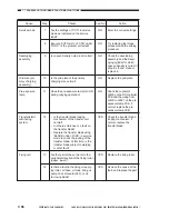
a. Check each of the charging assemblies for dirt.

Check the charging wire/grid plate for a fault
(damage, deformation).

b. Check shield plate of each charging assembly.

(If necessary, dry wipe the part with lint-free
paper; then, use alcohol. If the dirt cannot be
removed, replace the part.)

c. Check the height of each charging wire.
d. Make sure that each charging assembly is

properly set.

e. Check the charging spring (especially of the

separation charging assembly) for rusting.

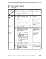
5. Checking the Developing Assembly

a. Check to make sure that the surface of the de-

veloping cylinder is covered with a uniform
coating of toner.

6. Checking the Paper

a. Check if the paper is of a type recommended

by Canon.

b. Check if the paper is moist.

Try making copies using fresh paper.

7. Checking the Periodically Replaced

Parts

a. Check the periodically replaced parts against

the Scheduled Servicing Chart, and replace
those that reached the end of their lives.

A. Initial Checks

1. Checking the Site of Installation

a. Make sure that the voltage at the power source

is as rated (±10%).

b. Make sure that the site is not subject to high

temperature/humidity (near a water
faucet,water boiler, humidifier) and is not cold,
not  close to a source of fire, and not subject to
dust.

c. Make sure that the site is not subject to ammo-

nium gas.

d. Make sure that the site is free of direct rays of

the sun; otherwise, curtains are provided.

e. Make sure that the room is well ventilated.
f.

Make sure that the machine is kept level.Make
the above checks to see if the site meets the
requirements.

2. Checking the Originals

Try to find out whether the problem is due to the

type of original used or to the machine.
a. Check the density of the originals; for example)

a diazocopy original or an original with trans-
parency can produce copies that tend to be
mistaken for “foggy copies”; and originals pre-
pared in light pencil tend to produce copies that
tend to be mistaken for “light image copies.”

3. Checking the Copyboard Cover,

Copyboard Glass, and Standard
White Plate

Check the copyboard cover,copyboard glass,

and standard white plate for dirt. Clean the part if
soiled, and replace the part if damage is found.

Summary of Contents for Vizcam 1000

Page 1: ...COPYRIGHT 2001 CANON INC CANON CLC1000 1000S 3100 REV 2 MAY 2001 PRINTED IN JAPAN IMPRIME AU JAPON REVSION 2 MAY 2001 FY8 13E3 020 COLOR LASER COPIER 1000 1000S 3100...

Page 2: ...OR THOSE FOUND IN ADVERTISING AND OTHER PRINTED MATTER ANYQUESTIONSREGARDINGINFORMATIONCONTAINEDHEREINSHOULDBEDIRECTED TO THE COPIER SERVICE DEPARTMENT OF THE SALES COMPANY COPYRIGHT 2001 CANON INC Pr...

Page 3: ...Copier 1000 1000S 3100 may be configured with the following system devices 1 Preview Monitor Preview Monitor Board 2 RDF E1 3 Editor F1 4 Film Projector B1 5 Stapler Sorter F1 6 Buffer Pass Unit 1 7...

Page 4: ...n how to install the CLC1000 1000S 3100 CHAPTER 6 Maintenance and Inspection provides tables of periodically replaced parts and consumables durables as well as scheduled servicing chart CHAPTER 7 Trou...

Page 5: ...vel of a given signal is High while 0 is used to indicate Low The voltage value however differs from circuit to circuit In addition the asterisk as in DRMD indicates that the DRMD signal goes on when...

Page 6: ...4 7 13 14 9 10 11 12 6 5 1 Preview Monitor 2 RDF E1 3 Editor F1 4 Film Projector B1 5 Stapler Sorter F1 6 Buffer Pass Unit 1 7 Paper Deck option in Japan 8 Control Card V 9 Interface Board B1 B2 Prev...

Page 7: ...9 B Pre Fixing Charging 2 9 C Grounding Roller 2 10 D Static Eliminator 2 10 E Transfer Belt Cleaning 2 11 III LIMITATIONS 2 12 A Outline 2 12 B Characteristics 2 12 CHAPTER 3 OPERATION AND TIMING I...

Page 8: ...III CHARGING SYSTEM 4 78 A Primary Charging Assembly 4 78 B Separation Pre Fixing Assembly 4 79 IX PROCESS UNIT SYSTEM 4 80 A Process Unit 4 80 B Cleaning Assembly 4 85 C Developing Assembly 4 87 D Ph...

Page 9: ...Service Mode COUNTER 6 7 III SCHEDULED SERVICING PROCEDURE 6 8 IV SCHEDULED MAINTENANCE CHART 6 9 CHAPTER 7 TROUBLESHOOTING IMAGE FAULTS MALFUNCTIONS GUIDE TO TABLES 7 1 I MAINTENANCE AND SERVICING 7...

Page 10: ...ONTROLLER PCB A 51 F CCD DRIVER CIRCUIT DIAGRAM A 66 G HVT CIRCUIT DIAGRAM A 70 H SPECIAL TOOLS A 82 I SOLVENTS AND OILS A 84 H Variable Resistors VR Light Emitting Diodes LED and Check Pins by PCB 7...

Page 11: ...GENERAL DESCRIPTION I FEATURES 1 1 II SPECIFICATIONS 1 2 A Type 1 2 B Mechanisms 1 2 C Performance 1 3 D Others 1 5 III LASER AND SAFETY MEASURES 1 9 A DHHS 1 9 B CDRH 1 9 C Points to Note When Handli...

Page 12: ......

Page 13: ...r deck 4000 sheets offers a source ready to supply 5000 sheets of paper 3 Automatic duplexing mechanism The built in duplexing unit enables automatic copying on both sides of sheets 4 Paper of up to 2...

Page 14: ...e medium OPC drum 60 dia Table 1 201 B Mechanisms Copying Indirect electrostatographic Charging Corona Exposure Laser beam Contrast adjustment Automatic Development Toner projection brush development...

Page 15: ...ecial LTR 279 mm x 216 mm Plainpaper 80to105g m2 transparency special Thinpaper 64to79g m2 Thin paper 64 to 79 g m2 plain paper 80 to 105 g m2 thick paper 106 to 163 g m2 including cast coated paper p...

Page 16: ...djustment density range adjustment Text printed photo text halide photo text printed photo halide photo map Size position Auto paper selection auto cassette change Page separation free division enlarg...

Page 17: ...XXXXXX CLC1000S AMS PGN XXXXXX CLC1000 ITA PHN XXXXXX CLC1000S ITA PFH XXXXXX CLC1000 general RGT XXXXXX CLC1000S general 240V QFH XXXXXX CLC1000 UK QCK XXXXXX CLC1000S UK RFH XXXXXX CLC1000 CA RCM XX...

Page 18: ...001 CANON INC CANON CLC1000 1000S 3100 REV 2 MAY 2001 PRINTED IN JAPAN IMPRIME AU JAPON Figure 1 201 2013mm w paper deck 1384mm 2476mm 820mm w sorter w projector 730mm Height 1000 mm w copyboard cover...

Page 19: ...B4 A4R B5R Enlargement B4 A3 B5R A4R B5 A4 A4R B4 A5 B5 A4R A3 B5R B4 A5 A3 LGL 279 mm x 432 mm 11 x 17 LTRR 279 mm x 432 mm 11 x 17 MINIT LTRR A4R A3 A5 A3 B4 A3 B5R A4R B5 A4 A4R B4 A5 B5 A4R A3 B5R...

Page 20: ...ossy Standard Glossy Standard Glossy Standard Glossy Standard Copying speed A4R LTR A3 A4R B4 279mm x 432mm 11 x17 15 6 9 31 12 18 24 9 4 6 6 4 4 15 31 9 21 9 12 9 4 6 21 9 12 9 4 6 9 4 6 6 4 4 6 4 4...

Page 21: ...PAREIL A RAYONNEMENT LASER DE CLASSE 1 LASER KLASSE 1 PRODUCTOLASERDECLASE1 APPARECCHIOLASERDICLASSE1 INACCORDOCONLANORMA CEI76 2 B CDRH On August 2 1976 the Center for Devices and Radiological Health...

Page 22: ...th the front left door open the shutter needs to be held open using a door switch actuator Keep these in mind when such work is necessary Figure 1 303 DANGER Laser radiation when open AVOID DIRECT EYE...

Page 23: ...CRIPTION IV NAMES OF PARTS A External View 1 Original tray 7 Control key power switch 2 Control panel 8 Front cover right 3 Editor option 9 Cassette 1 4 Hopper cover toner supply opening 10 Cassette 2...

Page 24: ...D IN JAPAN IMPRIME AU JAPON 1 Fixing assembly knob 7 Pre duplexing feeding assembly 2 Copy counter 8 Waste toner box 3 Front cover switch 9 Fixing delivery reversing unit 4 Hopper assembly 10 Fixing o...

Page 25: ...TED IN JAPAN IMPRIME AU JAPON 1 13 1 GENERAL DESCRIPTION 11 12 13 14 15 16 17 18 19 21 23 25 27 29 31 20 22 24 26 28 30 32 33 35 37 55 56 57 58 40 39 59 60 61 62 63 34 36 38 40 41 42 43 45 47 49 51 53...

Page 26: ...ion mirror 27 Y BD mirror 28 Registration roller 29 Thick paper detection roller 30 Multifeeder feeding roller 31 Multifeeder pick up roller 32 Multifeeder tray 33 Delivery vertical path roller 34 Dup...

Page 27: ...op key 5 Pre Heat key 6 Interrupt key 7 Start key 8 Clear key 9 ID key 10 Call key 11 Pilot lamp Description Press the appropriate key to select a specific copying mode Indicates the selected copying...

Page 28: ...holding at the edge Fan out each stack before setting it in a cassette or the multifeeder Remove from the tray immediately after copying to avoid jamming Keep unused transparencies in a box and store...

Page 29: ...tep 1 2 3 D Primary Charging step 2 2 4 E Laser Exposure step 3 2 4 F Development step 4 2 5 G Retention Transfer step 5 2 6 H Separation step 6 2 7 I Fixing step 7 2 7 J Photosensitive Drum Cleaning...

Page 30: ......

Page 31: ...ging assembly Pre exposure lamp Photosensitive drum cleaner Laser exposure Transfer belt Photosensitive drum Pre primary charging assembly Fixing assembly Pre fixing feeding Separation charging assemb...

Page 32: ...senting the corresponding process color of toner complementary to the corresponding filter for transfer to paper the step is executed alike for Y M C and K The resulting image is fixed to the paper pr...

Page 33: ...the original Such an image created on the photosensitive drum using differences in potential is not visible to the human eye and is called a static latent image Figure 2 103 C Pre Exposure step 1 Figu...

Page 34: ...harged photosensitive drum is determined by the potential of the grid a bias is applied to the grid to ensure a specific drum surface potential E Laser Exposure step 3 Figure 2 106 A laser beam of an...

Page 35: ...riction against the rotating cylinder The developer is held in the form of a brush over the surface of the cylinder within the magnetic field of the fixed magnet and is deposited in a uniform layer by...

Page 36: ...come into contact This is done by applying a high voltage constant current through a blade and onto the back of paper from behind the transfer belt The CLC1000 uses the same transfer charges to retai...

Page 37: ...Figure 2 112 Depending on the selected color mode a maximum of four transfers takes place before the paper is forwarded to the fixing assembly A pair of fixing rollers move the paper under pressure an...

Page 38: ...Drum Cleaning Figure 2 113 In preparation for the next copying run the cleaning blade scrapes off the residual toner from the surface of the drum The collected toner is moved by the waste toner feedi...

Page 39: ...arging to remove localized positive charges remaining on the photosensitive drum B Pre Fixing Charging Figure 2 202 The toner on the paper after separation is more or less neutralized and yet is subje...

Page 40: ...nd thereby to increase the efficiency of cleaning performed in the next step the belt is grounded by means of a grounding roller D Static Eliminator Figure 2 204 The transfer belt after separation of...

Page 41: ...ransfer belt cleaning web Polishing roller Oil removing roller Transfer belt Transfer belt cleaning blade Transfer belt cleaning web Oil removing roller Polishing roller Removes toner from the transfe...

Page 42: ...photosensitive drum is subject to the environment in which the machine is used and changes over time 2 Reflectance of Toner The ideal toners representing the primary colors yellow magenta and cyan sh...

Page 43: ...re system 3 64 C Laser Scanner Motor 3 65 D Generating the BD Signal 3 66 E Video Controller 3 67 F Laser Driver 3 72 G Image Position Correction 3 74 V IMAGE FORMATION SYSTEM 3 84 A Outline 3 84 B Ba...

Page 44: ......

Page 45: ...nating CCD driver Analog processor PCB Image processor PCB IP memory PCB To external device Laser driver PCB Laser scanner Video controller PCB Laser exposure block BK C M Y Separation Charging Pre ex...

Page 46: ...Lamp regulator Scanner motor driver PCB Video controller PCB Laser driver laser BD Board PCB Preview Monitor Board monitor DC controller PCB SALT sensor PCB Color toner density sensor Sensor Switch Dr...

Page 47: ...cessor PCB ECO PCB ECO PCB J 2001 J 2003 J 2501 J 2503 J 2502 J 1453 Interface PCB BD Y PCB Laser Y Laser driver M PCB BD M PCB Laser M Laser driver C PCB Laser driver K PCB Laser C Laser K BD C PCB B...

Page 48: ...g fan 2 Scanner assembly cooling fan 3 Scanner assembly cooling fan 4 5V J 1306A J 602A M 29 J 603 1 2 3 4 5 See Chapter 3 original exposure system J 602B 12 11 10 PS 37 FM 10 FM 12 FM 13 24V 8 9 FM 1...

Page 49: ...2 J 6283 J 6284 J 6286 J 6281 1 J 6263 1 J 6251 J 1302 2 2 Reader controller PCB 5V See Chapter 3 control panel DC controller PCB J 2206 J 1307 J 6244 J 1306B Copy Data Controller A1 PCB To Copy Data...

Page 50: ...3 J 6062 1 2 3 J 6064 1 2 3 J 6065 1 2 3 J 6076 1 2 3 J 6077 1 2 3 J 2214B 3 2 1 J 2214B 6 5 4 J 2953B 3 2 1 J 2954 3 2 1 J 2954 4 5 6 J 2954 7 8 9 PS1DT PS2DT PS3DT PS4DT PS5DT DC controller PCB Whe...

Page 51: ...1 2 3 J 6107 1 2 3 J 6108 1 2 3 J 6109 1 2 3 J 6110 1 8 5 6 13 J 2218B 1 J 2219A 7 J 2219B 1 J 2219A 8 PS 16 J 2219B 2 3 7 8 Alternates between 1 and 0 while transfer belt cleaning web drive motor is...

Page 52: ...PS 28DT J 6168 1 2 3 J 6125 1 2 3 J 6126 1 2 3 J 6127 1 2 3 J 6128 1 2 3 J5500B 12 11 10 J 6129 1 2 3 9 8 7 J 6130 1 2 3 J 6131 1 2 3 6 5 4 3 2 1 J 6172 1 2 3 6 8 7 9 12 10 11 8 7 6 5 2 4 3 PS 29DT P...

Page 53: ...pper fixing falls short of specific value 1 when light blocking plate is at PS36 5V PS 38 J 6273 1 2 3 PS 38DT J 2211B 9 8 7 Delivery vertical path sensor 1 When paper is at PS38 1 when light blocking...

Page 54: ...r length sensor unit C2SZ0 C2SZ1 J 6160L 1 2 4 3 J 2226B 8 5 6 7 J2209B 10 TS 1 J 6337 3 2 1 YTEPU J3401A 1 2 3 TS 2 TS 8 J 6330 3 2 1 J 6332 3 2 1 YTEP 8 C toner level sensor upper CTEPU TS 3 J 6334...

Page 55: ...V EPC M Potential sensor M M potential measurement PCB Y potential measurement PCB 2 1 2 3 3 150V 15V 15V 150V 15V 15V J 4604L 1 J 6219M 2 1 2 3 3 FRDC J 2212B 14 15 SW 1 Front cover switch Control ke...

Page 56: ...sensor K J 6063 5 1 3 4 6 2 24V J 2953B 5 9 7 J 6224Y 6 4 8 EV1 Environment sensor EVRMT EVHUM EVTEMP 150V 15V 15V 150V 15V 15V J 4604R 1 J 6219K 2 1 2 3 J 2955B 6 J 2207B 10 7 8 8 10 9 6 J 6099Y J 62...

Page 57: ...3F J 2951R J 2854R J 2204 See Chapter 3 laser exposure See Chapter 3 laser exposure SALT Y SALT M SALT C SALT K ATR Y ATR M ATR C J 6099M J 6099Y J 6099C J 6099K J 2228A J 2228A J 2228B J 2228B J 6158...

Page 58: ...ON LHON When 1 cassette heater Paper deck heater turns ON When 1 Bk drum heater turns ON When 1 C drum heater turns ON When 1 M drum heater turns ON When 1 Y drum heater turns ON When 1 M30 turns ON W...

Page 59: ...e leaves transfer belt J 2220 1 2 SL 7Y SL7YDS When 0 SL7YDS turns ON transfer blade comes into contact with transfer belt J 6101 1 2 3 SL7YDR When 0 SL7YDR turns ON transfer blade leaves transfer bel...

Page 60: ...J 6169 2 1 Duplexing paper deflecting plate solenoid R SL 11R SL11RD When 0 SL11M turns ON J 6170 2 1 Duplexing paper deflecting plate solenoid L SL 11L SL11LD When 0 SL11L turns ON J 6171 2 1 13 Stop...

Page 61: ...opens SL17CDC When 0 SL17CDC turns ON shutter closes SALT sensor shutter open close solenoid for Bk 24V SL 17Bk J 6313 3 2 1 SL17KDO When 0 SL17BDO turns ON shutter opens SL17KVDC When 0 SL17BDC turns...

Page 62: ...1 turns ON CL 12 CL12D J 6137 2 1 Cassette 1 pick up clutch J 2222A 9 24V When 0 CL12 turns ON CL 13 CL13D J 6138 2 1 Pick up vertical path roller 2 clutch J 2222A 10 24V When 0 CL13 turns ON J 5501A...

Page 63: ...ing fan rear 24V J 2208B 8 9 FM 6 FM6D When 0 FM6 turns ON J 6041 1 2 J 2233 1 2 24V Primary exhaust fan Primary suction fan left Primary suction fan right FM 7 FM7D When 0 FM7 turns ON J 6073 2 1 Pre...

Page 64: ...tes between 1 and 0 while M3 is rotating M 4 Laser scanner motor Laser scanner motor driver PCB See Chapter 3 laser exposure M 5 Image position correction mirror slant correction motor for C 24V J2210...

Page 65: ...2218A 11 10 9 12 M15ON M15PLL M15DIR J 6100 5 6 3 2 1 4 J 2213A 8 9 10 11 24V Pick up motor J6091 2 1 J 2218A 1 4 24V Pre fixing feeding motor M12D 24V J2219A 2 5 1 3 4 6 M13 A M13 A M13 B M13 B While...

Page 66: ...M 18Bk J 2223B 4 5 6 Bk developing motor M18BkPLL M18BkON J6145Y 3 2 1 M 18Y J 2226A 6 7 8 Y developing motor M18YPLL M18YON J6145M 3 2 1 M 18M J 2226A 9 10 11 M developing motor M18MPLL M18MON J6146...

Page 67: ...2 1 Duplexing reversing motor J 6021Y 3 1 LA 1 LA1ON When 0 LA1 turns ON Pre exposure lamp Y 24V J 2239A 1 2 LA 2 LA2ON When 0 LA2 turns ON Pre exposure lamp M 3 4 J 6021M 3 1 LA 3 LA3ON When 0 LA3 t...

Page 68: ...B 11 5 6 7 8 9 10 12 J 4602R 2 8 7 6 5 4 3 1 Primary charging assembly C 24V Primary charging assembly Bk T 4603 T 4602 J 4605 T 4605 J 4606 T 4606 HVPPRC HVGRC HVPRC HVPPRK HVGRK HVPRK When 1 respect...

Page 69: ...0 11 9 13 J 5102 2 4 3 5 1 24V Separation charging assembly J 5103 HVSPAC HVSPDC HVSPEN HVACEN HVSRD When 1 pre fixing high voltage is generated HVT5 PCB J 2217B 11 10 12 J 5201 2 3 1 24V J 5103 HVPRF...

Page 70: ...temperature reaches 110 C a transfer belt home position search is executed at the end of which image position correction will start The fixing temperature means the surface temperature of the fixing...

Page 71: ...surface temperature of the upper fixing roller reaches 110 C From when the surface temperature of the upper fixing roller has reached 110 C until it reaches 180 C From the end of INTR until the Start...

Page 72: ...nsferred to the paper From the end of COPY until the main motor stops Purpose Executes scanning for an original and shading correction Measures and controls the drum surface potential Picks up paper T...

Page 73: ...n originals are exposed and when the reflected light is directed to the CCD Figure 3 201 shows a cross section of the original exposure system and Figure 3 202 shows its exterior view Figure 3 201 Fig...

Page 74: ...iginal standard mode marking A Shading correction B Original position detection black original detection AE measurement C Original scanning D Marking area scanning Figure 3 203 Scanning lamp Original...

Page 75: ...tion Table 3 201 The original scanner home position sensor turns on At power on At start of copying At end of original scanning During CCD adjustment service mode Figure 3 204 Original scanner home po...

Page 76: ...nce and reproduction data from the image processor PCB Then in response to the start command it sends drive pulses to the scanner motor to suit these data units The scanner motor is a 5 phase stepping...

Page 77: ...en writing them to line memory reduction or repeating them when reading from line memory enlargement The reproduction ratio in the sub scanning direction is changed by moving the mirror mount fast red...

Page 78: ...gainst fluctuations in voltage Figure 3 207 2 Operations a Turning ON OFF the Scanning Lamp The lamp regulator drive circuit turns OFF when LAON 0 causing the intensity control circuit and then the sc...

Page 79: ...to cut the power to the scanning lamp If an overcurrent flows because of a short circuit around the scanning lamp the fuse turns OFF thereby cutting off the power to the lamp regulator The thermal sw...

Page 80: ...nalog processor PCB used to generate digital video signals from analog video signals 3 Group of PCBs used to process digital video signals image processor PCB memory PCB Preview Monitor Board Figure 3...

Page 81: ...to converted The signal charges occurring after conversion are synchronized with the shift pulses generated by the analog processor PCB and stored temporarily in the transfer block single line then th...

Page 82: ...gain correction and offset correction specifically the output voltages in the absence of light are made even offset correction and the ratio of amplification is made constant to even out the photo con...

Page 83: ...ng c ECO PCB provided as standard Supports the image processor PCB for image processing d IP Memory PCB provided as standard Compresses and stores images single A3 page max e ED Board A1 option The in...

Page 84: ...by way of the image processor PCB The ED board A1 processes the image signals from the image processor PCB area processing text composition The communication with an external device e g IPU IPU II is...

Page 85: ...selector Bit map data Bitmap data Area data Control panel Editor Y M C Bk Color space correction Background removal Y M C conversion R G B Y M C text signal Y M C Bk Y M C Bk Image compression Image...

Page 86: ......

Page 87: ...der the standard white plate and determines the correction target value See Reference Figure 3 307 b The CCD measures the light reflected by the standard white plate and generates data representing th...

Page 88: ...lines on the copies If such a problem cannot be corrected after cleaning the standard white plate you may change the position of shading correction using ADJ S under ADJ XY in service mode b 3 Line CC...

Page 89: ...s so that only the area where there is an original reflects the light of the scanning lamp to the CCD Figure 3 314 Figure 3 315 In general most originals are white paper so that the area identified as...

Page 90: ...ge shifts If the RF is installed and an original is placed on the copyboard original position identification cannot be executed d Mirror Image Processing Figure 3 316 e Input Masking When light reflec...

Page 91: ...ration Figure 3 320 In the case of full integration image A which has been read by the scanner first is stored in the image memory first and integrated with image B which has been read next If image A...

Page 92: ...ne Width Identification In this block the width of the area text to which a specific pixel belongs is identified thereby enabling reproduction of naturally emphasized edges suited to the thickness of...

Page 93: ...ss that can be reproduced by the printer It checks the RGB data read by pre scanning and processes it so that it can fit the printer s color reproduction range With this arrangement the CLC1000 reprod...

Page 94: ...iginal if they tend to appear most frequently in the sample image data collected during pre scanning and in addition if the level of the R G and B signals is 200 or more Figure 3 324 Figure 3 324 Back...

Page 95: ...the output of the CCD as perceived by the eye To compensate for the discrepancy level conversion is executed as shown in Figure 3 326 Figure 3 325 Figure 3 326 b BGR YMC Conversion The circuit genera...

Page 96: ...and light patterns repeat in high density are called high frequency components on the other hand areas where dark and light patterns repeat in low density are called low frequency components Within im...

Page 97: ...nce in density between pixels will not vary excessively when producing enlarged copies Figure 3 331 shows image data of an original image data at time of enlargement and image data after enlargement c...

Page 98: ...ing to the read signal generated in relation to the ITOP signal and sent to the image processor after the UCR processing block has generated the Bk signal The image signals from an external device are...

Page 99: ...addition of the Bk signal to the Y M and C signals See discussions on YMC conversion Figure 3 333 The Bk signal is generated as follows The gray components of the YMC signals are as indicated in Figur...

Page 100: ...eristics for the B component and C toner likewise tends to have undesirable absorption characteristics for the G and the B components segments enclosed in Figure 3 336 In other words M toner if left a...

Page 101: ...k Setting sharpness to weak will smooth changes in the density of images making the copy image soft And if image data shown in Figure 3 337 is input the output level will be as shown Figure 3 339 with...

Page 102: ...mine which pixels of the image should be corrected In addition if a registered color has been selected by a color palette color data will be read from the bit map memory to represent the selected pixe...

Page 103: ...on image A which has been read by the scanner is converted into binary data by the ED Board A1 then bit map data is generated based on the area data The bit map data is temporarily stored in the bit m...

Page 104: ...c Color balance service mode COL ADJ d Light area offset adjustment service mode OFST under COL ADJ e Text photo mode As indicated in Figure 3 343 either a dark or light curve will be selected to suit...

Page 105: ...he CRT closer to each other by varying the image density signals In the image editing block the image data is rotated shifted or enlarged as specified on the control panel The area image generation bl...

Page 106: ...hich is synchronized for main and sub scanning directions by the video controller are converted by the laser driver into laser drive signals that represent the level of the signals The laser beam is g...

Page 107: ...bottom blocks generating four channels of laser beams as shown in Figure 3 402 Figure 3 402 Since the positions of the laser units and the direction of rotation of the polygon mirror differ for M Y a...

Page 108: ...tivated in relation to the image leading edge signal to form a latent image on the drum The PWM activation period is given a delay for each color to make up for the distance between drums When the PWM...

Page 109: ...er motor drive signal SMON goes 0 If the rotation speed of the motor is at a specific value the laser scanner motor ready signal SMRDY goes 0 indicating to the DC controller that the condition is norm...

Page 110: ...ction PCBs are used to deal with the four colors and the BD signal is generated for each channel Figure 3 406 In reference to the BD signal for each color the video signal is synchronized for the main...

Page 111: ...g direction based on the ITOP signal and are subjected to gamma correction based on the conversion table in the density correction RAM See Density Correction Of the video signals after density correct...

Page 112: ...BD signal for Y M C and Bk In the sample shown in Figure 3 410 the Y main scanning sync signal YSYNC is generated in sync with the Y BD signal YBD the read enable signal YRE is generated after a speci...

Page 113: ...d from the timing chart the read enable signal for each color is given a delay for the distance between drums The video signal is forced to remain 0 until the print area signal YFRM in Figure 3 411 is...

Page 114: ...thereby bringing the output characteristics closer to the ideal characteristics Figure 3 414 The correction curve for conversion is stored in the density correction RAM on the video controller in rel...

Page 115: ...g direction to generate video signals Figure 3 416 Address data for test patterns is generated in response to the ITOP signal and addresses are assigned in the RAM for gamma correction The selected vi...

Page 116: ...Bs has the following functions Laser Driver PCB 1 Generates the laser drive signals for 400 lines 200 lines 266 lines 2 Turns ON OFF the laser 3 Selects activation mode Laser Power Adjustment PCB 1 Mo...

Page 117: ...rent Since the activation current I varies according to the ambient temperature the intensity at the point of activation is monitored at all times and the activation current is controlled so as to mai...

Page 118: ...olors in the order of Y M C and then Bk Displacement of images can occur because of the following factors 1 Displacement in main scanning direction 2 Displacement in sub scanning direction 3 Discrepan...

Page 119: ...or by the CCD for reading patterns 3 Using the M pattern for reference analyzes each pattern to determine the degree of discrepancy using the CPU on the DC controller 4 Prepares correction data based...

Page 120: ...rns are formed on the transfer belt using the data as when creating regular images for copies As shown in Figure 3 422 patterns are formed along the front and the rear ends in the order of Y C M and B...

Page 121: ...for both main and sub scanning directions The coordinates of the center of the pattern is computed based on the data In the case of Figure 3 425 the center in the main scanning direction is the 128th...

Page 122: ...pattern interval of 7 mm for the C and Bk patterns see Figure 3 427 Thereafter the Y pattern is formed as soon as the photosensitive drum completes a half rotation When a total of 8 sets of patterns h...

Page 123: ...ns the shutter drive motor remains on for 5 sec once again to move the shutter to the closed position Figure 3 429 If the shutter open sensor dose not detect the light blocking plate when the shutter...

Page 124: ...ot 0 Here correction is made so that the angle will be closer to 0 Figure 3 430 The correction is made by changing the tilt of the image position correction mirror thereby changing the scanning angle...

Page 125: ...o be incorrect Here correction is made so that Ly will be closer in value to Lm Figure 3 432 The correction is made by shifting the image position correction mirror horizontally thereby changing the l...

Page 126: ...to the start of M Figure 3 434 The correction is made by changing the read timing T1 in Figure 3 435 for the Y C and Bk video signals In the case of Figure 3 434 T1 is extended thereby delaying the st...

Page 127: ...rrection is made so that X will be closer to 0 In the case of Figure 3 437 the Y start position will be advanced until it is the correct position Figure 3 437 The correction is made by varying the rea...

Page 128: ...is obtained by the following sensors Environment Sensor Measures the temperature humidity inside the machine Corrects the grid bias separation charging bias and transfer blade bias Potential Sensor Me...

Page 129: ...late 4 HVT4 Supplies a DC AC bias to the separation charging unit 5 HVT5 Supplies a DC bias to the pre fixing charging unit The external static eliminating roller is grounded in relation to the intern...

Page 130: ...ntrol Potential correction SALT Drum motor Pre exposure lamp Pre primary charging bias Primary charging bias Grid bias Developing motor Y Developing motor M Developing motor C Developing motor Bk Deve...

Page 131: ...iases are determined with reference to the data from the potential sensor during copying the grid bias is corrected based on the data from the environment sensor The grid bias and the developing bias...

Page 132: ...eal contrast potential initial potential control thereafter the appropriate grid bias is determined each time the Start key is pressed thereby correcting changes over time potential correction Figure...

Page 133: ...discussed the timing of measurement is as follows Figure 3 509 Video signals set to 00H and FFH Power switch turned ON Vg set to 300 V Vd and VL measured Vg set to 700V Vd and VL measured Grid bias Vg...

Page 134: ...ical to the target contrast potential is detected and the point is used to obtain the target value of the grid and developing biases in the case of Figure 3 511 V1 and V2 are target values Figure 3 51...

Page 135: ...each color with reference to the measurements taken and the pre determined contrast potential The detail codes of E061 are explained below according to procedure for drum surface potential control and...

Page 136: ...V or more Difference of the measured value of VL2 is 30 V or more VD1 is 500 V or more and in addition VD2 is 900 V or more VD1 is 900 V or more and in addition VD2 is 900 V or more VD1 is 200 V or l...

Page 137: ...s Difference between previous VD and newly computed VD is 30 V or more Difference between previous VG and newly computed VG is 30 V or more V00 is upper limit 950 V or more V00 is lower limit 325 V or...

Page 138: ...sured by the SALT sensor and the toner supply period is corrected based on the resulting measurements Figure 3 514 Figure 3 515 Y M C Bk SALT sensor SALT sensor ATR sensor Transfer belt SALT sensor SA...

Page 139: ...00 or higher measurements are taken after each 100 copies have been made Figure 3 516 The SALT sensor measures the density of toner and computations are made to find out whether the current toner dens...

Page 140: ...ion Test Print 1 halftone and solid patch Figure 3 518 2 Referring to the halftone area of the generated Test Print 1 check for differences in density and faults in images if an error is found make ad...

Page 141: ...mbly The charge current for the primary corona wire and the pre primary corona wire and the grid bias is controlled by the control signal from the DC controller The change current for the primary coro...

Page 142: ...ending pulse output to the transformer The transformer is driven Corona current sent to the primary charging assembly The output of the primary corona current is monitored with reference to its curren...

Page 143: ...igure 3 522 Figure 3 522 The output of the grid bias is monitored with reference to its voltage and the data is fed back to the current control circuit The feedback signal is used to ensure a specific...

Page 144: ...ona current that suits the voltage of HVPPR is generated The output of the pre primary current is monitored with reference to its current value and the data is fed back to the variable pulse oscillato...

Page 145: ...cleaning mechanism is activated in user mode When 5000 copies have been made since the previous cleaning operation Figure 3 525 When the control signal from the DC controller is M24FW 1 M24RV 0 the p...

Page 146: ...C developing assemblies infrared light is shone on the toner layer on the developing assemblies and the reflected light is measured to determine the amount of toner to supply on the other hand in the...

Page 147: ...AC bias is generated so that it assumes the wave forms shown in Figure 3 528 Both DC and AC biases are controlled by control signals from the DC controller for application The DC bias to the stray to...

Page 148: ...f as follows Transformer drive signal HVON 1 and developing AC bias enable signal HVACEN 1 The transformer is driven and 1kV is sent to the AC bias generation circuit An AC bias is generated based on...

Page 149: ...V is sent to the voltage control circuit The output from the transformer is controlled to suit the voltage of HVDC and is applied to the developing cylinder The DC bias output signal HVDC and the dev...

Page 150: ...f by the stray toner collection DC bias drive signal HVSRD as follows HVSRD 1 The variable width pulse oscillator circuit turns ON and pulse output is sent to the transformer The transformer is driven...

Page 151: ...ereby computing toner consumption When copying operation ends the SALT sensor measures the toner image on the photosensitive drum to find out the toner density Figure 3 532 See Figures 3 533 and 534 f...

Page 152: ...sorb it In other words when the amount of toner decreases because of consumption over time the reflection of infrared light will decrease because of the changing toner carrier ratio of the developer U...

Page 153: ...ght REF M level remains the same By comparing the reflected intensity SGNL M and its initial value a voltage corresponding to the density of the toner is computed and used as the toner density signal...

Page 154: ...play mode DISPLAY Developer density DENS Item Description Reference SGNL Y Toner layer reflection intensity 700 to 912 SGNL M Toner layer reflection intensity 700 to 912 SGNL C Toner layer reflection...

Page 155: ...motor moves through the toner supply screw to supply toner to the developing assembly This operation is executed while the developing cylinder is rotating after measuring the density of toner The dura...

Page 156: ...when the toner level falls below the sensor issues the message ADD TONER on the control panel when copying operation ends Figure 3 540 The rear sensors error sensors TS1 2 3 look for sensor faults or...

Page 157: ...lied based on the amount of consumption computed with reference to the count of the video signals carrying a Bk component As shown in Figure 3 541 the video signals from the image processor are counte...

Page 158: ...e are corrected in the same way as for color toner Since the window of the sensor tends to become soiled with stray toner correction is made for the dirt on the window also The LED is turned on during...

Page 159: ...um Detection of reflected light LED SGNL S K LEDON REF S K CPU Toner supply signal Toner density signal DC controller PCB Q1 Corrects for dirt on the window During copying operation the density is mea...

Page 160: ...Dirt on the Window The LED is turned on during last rotation LSTR after copying operation so as to measure the light reflected from the photosensitive drum without toner on it SGNL D K If the sensor...

Page 161: ...so that the supply period amount will be less if the measurement is lower than the ideal density too little toner on the other hand opposite correction is made to supply a larger amount of toner Figu...

Page 162: ...ensity of toner inside the developing assembly is below a specific value the DC controller sends the toner supply signal to turn on the toner supply clutch As a result the drive of the Pick up motor w...

Page 163: ...When a specific period of time passes after toner supply operation the signal from the sensor is read by the DC controller if the absence of toner is detected the sub hopper starts to supply toner If...

Page 164: ...r motor Figure 3 552 Photosensitive drum Waste toner feeding screw Cleaner blade M20 Waste toner feeding motor M18Bk M18C M18M M18Y Developing motor Y Developing motor Bk Developing motor M Developing...

Page 165: ...ided The gear A Figure 3 553 used to drive the waste toner feeding screw shifts over the shaft because of the axial force that occurs when the feeding screw locks The shift of the gear A is checked by...

Page 166: ...g current to the internal static removing roller and the charging current to the separation charging corona wire and the pre fixing charging corona wire are all controlled by the control signals from...

Page 167: ...ransfer current is generated The output of transfer current is monitored by its current value and the data is fed back to the transistor Q1 The feedback signal is used to control the transformer drive...

Page 168: ...r is driven and a DC bias suited to the voltage of HVER is generated The output of the internal static current is monitored by its voltage value and the data is sent to the transistor Q1 in the form o...

Page 169: ...to the voltage level of HVSPEDC is generated HVSPAC 1 The pulse circuit turns on and pulse output is sent to the transformer for AC The transformer for AC is driven A bias for separation is generated...

Page 170: ...ME AU JAPON 3 126 Figure 3 557 HVT4 DC controller PCB Pulse oscillator circuit Transformer for DC Pulse oscillator circuit 24V 24V HVSPDC HVSPAC Transformer for AC 24V Current detection circuit Voltag...

Page 171: ...registration roller so that its leading edge and the leading edge of the image on the photosensitive drum match and is then sent to the transfer belt Upon reaching the transfer belt the paper is reta...

Page 172: ...PS15 Pre fixing feeding assembly Photosensitive drum Bk Photosensitive drum C Photosensitive drum M Photosensitive drum Y Transfer belt PS30 Holding tray duplexing unit Feeding roller PS21 PS29 PS31...

Page 173: ...e holding tray feeding sensor 2 Post registration paper sensor Separation sensor Pick up vertical path 1 sensor Cassette 1 paper sensor Cassette 1 lifter sensor Pick up vertical path 2 sensor Notation...

Page 174: ...idth detecting VR operate in association with the width guide plate and the length guide plate inside the cassette and adjusting these guides to suit the paper will establish the positions of the boss...

Page 175: ...ugh M as shown in Table 3 602 Use the markings to find out if the paper guide plate is correctly set to suit the paper being used if a user calls to report skew movement This information is not made o...

Page 176: ...me of shipment from the factory Table 3 604 e Registering the Paper Width Basic Settings See chapter 7 II Standards and Adjustments G 1 Registering the Casstte Multifeeder Paper Width Basic Setting Pa...

Page 177: ...per Then the pick up roller releasing solenoid turns on so that the pick up roller leaves the surface of the paper After pick up a single sheet of paper is forwarded to the feeding path by the feeding...

Page 178: ...r plate drive signal SL12D Cassette 2 pick up roller drive signal CL14D Pick up vertical path roller 3 drive signal CL15D Registration roller release signal SL16D Paper thickness detection roller driv...

Page 179: ...etect the top surface of the stack of paper on the lifter When paper runs out and the paper detecting lever leaves the paper sensor the message ADD PAPER will be indicated on the control panel The not...

Page 180: ...Y 2001 PRINTED IN JAPAN IMPRIME AU JAPON 3 136 Figure 3 606 M Cassette lifter motor M10 Paper Cassette paper sensor Pick up roller Paper detecting lever Pick up roller Lifter Lifter detecting lever Li...

Page 181: ...ertical path 2 sensor PS25 Pick up vertical path 1 sensor PS21 Transparency sensor OHPS Registration paper sensor PS1 Registration roller clutch CL8 Post registration paper sensor PS14 Start key ON CN...

Page 182: ...eeder pick up roller releasing solenoid SL5 turns on moving the pick up roller away from the surface of the paper A single sheet of paper is moved by the feeding roller and the separation roller to th...

Page 183: ...to how long the registration paper sensor PS1 remains ON The slide guide front and the slide guide rear each are equipped with a multifeeder paper sensor PS4 PS5 to check the presence absence of pape...

Page 184: ...timing so that the multifeeder lifter lowers until the multifeeder lifter sensor lower PS3 turns ON When paper is absent for supply of paper When a jam has occurred for jam removal When copying ends f...

Page 185: ...kness detecting roller upper when paper is not moving through the paper thickness detecting roller The difference in the angle of the light of the LED reflected by the paper thickness detection roller...

Page 186: ...ect Figure 3 612 Start key ON CNTR COPY Photosensitive drum M21 Pick up motor M10 Multifeeder paper sensor PS4 PS5 Multifeeder lifter motor M1 Multifeeder lifter sensor upper PS2 Multifeeder pick up r...

Page 187: ...e identified as being transparencies or not by the registration paper sensor PS1 and the transparency sensor in front of the registration roller When they are identified as transparencies the fixing s...

Page 188: ...moved on the transfer belt the registration roller releasing solenoid SL16 turns on As a result the drive of the pick up motor is transmitted to the registration releasing arm by way of the spring cl...

Page 189: ...4 LTR B5 80 g m2 at once and picks up and feeds paper to the copier body in response to control signals from the DC controller PCB The lifter of the paper deck is driven by the paper deck motor M8001...

Page 190: ...hen the paper deck feeding roller clutch CL8001 turns on to forward the paper to the registration roller The registration roller controls the paper so that its leading edge and the image on the photos...

Page 191: ...ck up from paper deck Paper Deck A4 LTR 2 Copies in Continuous 4 Color Direct Figure 3 617 CNTR Start key ON COPY Photosensitive drum motor M21 Pick up motor M10 Paper deck pick up feeding clutch CL80...

Page 192: ...r stacked on the lifter When paper runs out and the sensor arm blocks the paper absent sensor PS8001 the message ADD PAPER will be indicated on the control panel At this time the lifter will move up u...

Page 193: ...ection circuit is provided to force off the paper deck motor if a short circuit or the like allows an overcurrent to flow into the motor When the circuit has activated the copier may be reset by remov...

Page 194: ...y the CPU changes from 0 to 1 The condition causes the lifter up signal STMUP to go 0 and the lifter down signal to go 1 thereby lowering the lifter At this time the lifter will not move down to its l...

Page 195: ...es of paper Figures 3 620 and 621 show diagrams of the duplexing unit and the operation of the duplexing unit Figure 3 620 Figure 3 621 Delivery vertical path assembly Duplexing reversing assembly Pre...

Page 196: ...g tray duplexing unit moves up by the drive from the duplexing unit pick up solenoid SL8 the stopper plate on the other hand shifts up by the drive of the duplexing unit stopper plate solenoid SL18 Th...

Page 197: ...23 PS32 PS33 PS8 PS9 PS30 PS29 PS31 PS21 SL13 SL8 Duplexing pick up roller releasing solenoid Feeding roller solenoid M19 Duplexing feeding motor SL12 Stopper plate solenoid SL11L SL11R SL11S Duplexin...

Page 198: ...ath may be any of four created by three paper deflecting plates Each paper deflecting plate is driven by its own solenoid Table 3 607 The CLC1000 s two sided copying mode does not accommodate A5 size...

Page 199: ...9 The DC controller PCB then sends pulses in numbers appropriate to the size of paper to the motor In response the motor starts to rotate clockwise to move the paper guide plate to suit the copy size...

Page 200: ...INC CANON CLC1000 1000S 3100 REV 2 MAY 2001 PRINTED IN JAPAN IMPRIME AU JAPON 3 156 Figure 3 626 Putting Paper in Place Paper guide plate rear 8mm 8mm Paper Paper guide plate rear CW rotation 8mm 8mm...

Page 201: ...M21 Internal delivery sensor PS35 Delivery paper deflecting plate solenoid SL14 Waste toner motor M20 Duplexing reversing motor M28 Duplexing feeding motor M19 Pre holding tray feeding sensor 1 PS8 D...

Page 202: ...ed to the pick up roller starting pick up operation After pick up the duplexing pick up roller releasing solenoid SL8 operates to move the pick up roller away from the surface of the paper A single sh...

Page 203: ...4 Color Direct Figure 3 629 Start key ON 2nd side CNTR COPY Photosensitive drum motor M21 Holding tray paper sensor 2 PS31 Duplexing pick up roller clutch CL10 Pick up vertical path 1 sensor PS21 Reg...

Page 204: ...position of the transfer belt Corrects displacement of the transfer belt Operates the lifter of the transfer belt Cleans the transfer belt Figure 3 630 Photosensitive drum Bk Photosensitive drum C Ph...

Page 205: ...d at the same time generates the transfer belt motor reference pulse signal M14PLS When M14D and M14PLS are input to the motor drive pulse generator circuit on the transfer belt motor driver PCB motor...

Page 206: ...ansfer belt When the registration roller clutch CL8 turns on the transfer blade is put in transfer position for retention of paper and transfer The transfer blade is put in and out of position by the...

Page 207: ...adversely affect the images because of uneven charging efficiency To prevent such a problem a seam detection sticker is put on the transfer belt When the Start key is pressed the transfer belt home po...

Page 208: ...nsparency Matte Standard Glossy Standard Matte Standard Glossy Standard Glossy Standard Glossy Standard Glossy Standard Glossy Standard Source of paper One sided two sided Type of paper Shine Mode of...

Page 209: ...r Belt A4 A3 A3 A3 A4R A4R B4 Mode A 31 cpm Mode B 12 cpm Mode C 18 cpm A4 Mode D 15 cpm Mode E 6 cpm A4R B4 A4 A4 Mode F 9 cpm Mode G 4 cpm 543 1320 Seam Seam Seam 1st rotation 2nd rotation 3rd rotat...

Page 210: ...U JAPON 3 166 A4 A3 Mode H 9 cpm Mode I 21 cpm 543 1320 1st rotation 2nd rotation 3rd rotation 15 15 132 132 645 675 645 675 330 315 345 330 330 330 315 345 Seam Seam Seam Feedimg direction Mode J 24...

Page 211: ...d sensor 3 front PS19 and the transfer belt end sensor 4 rear PS20 are used See Figures 3 635 636 and 637 for diagrams of the mechanism used to correct displacement of the transfer belt from detecting...

Page 212: ...6 b Displacement to the Front The transfer belt swing motor operates the drive arm to move the swing roller to the left thereby returning the transfer belt to the rear Figure 3 637 The transfer belt s...

Page 213: ...as been measured the transfer belt is moved up back to the point of transfer The lifter movement is monitored with reference to the light blocking plate mounted to the cam shaft detected by the transf...

Page 214: ...1000S 3100 REV 2 MAY 2001 PRINTED IN JAPAN IMPRIME AU JAPON 3 170 Table 3 610 Transfer belt position Lower escape position Upper normal position Transfer belt lifter sensor 1 PS12 H L Transfer belt li...

Page 215: ...oil a cleaning mechanism is installed See Figure 3 639 Figure 3 639 Photosensitive drum Bk Photosensitive drum C Photosensitive drum M SL18 Photosensitive drum Y Drive roller M12 Oil removing roller P...

Page 216: ...nsfer cleaning blade solenoid SL6 only at the time of image position correction Once set to position the cleaning blade remains as is but moves away from the transfer belt released over the seam The t...

Page 217: ...leaning web rotation sensor PS10 which monitors the clock plate on the external static eliminating roller shaft The length of the web is monitored by the transfer belt cleaning web length sensor PS11...

Page 218: ...solenoid SL18 turns on rotating the cam through the control ring and operating the push on spring The polishing roller is moved away from the transfer belt when the solenoid turns off to move the cam...

Page 219: ...gging To prevent such a problem the oil removing roller is used to remove fixing oil from the transfer belt in two sided copying mode or when paper is picked up from the multifeeder The oil removing r...

Page 220: ...nsfer belt cleaning web motor M12 Separation sensor PS15 ON for each 210 sec rotation of transfer belt ON or OFF Note Transfer blade set Transfer blade set Transfer blade set Transfer blade set Transf...

Page 221: ...ng feeding motor M11 to rotate two feeding belts to move paper To improve paper movement the pre fixing feeding fan FM7 is used to keep copy stable on the belt from behind the feeding belt The feeding...

Page 222: ...fixing web is driven by the upper fixing web take up solenoid SL3 and the lower web is driven by the lower fixing web motor M30 In addition the lower fixing roller is equipped with a spring locking ty...

Page 223: ...uring STBY controlled to 180 C During pre heat controlled to 180 C Figure 3 647 M30 DC controller PCB CPU Upper fixing heater drive signal UHON Lower fixing heater drive signal LHON Triac error detect...

Page 224: ...short circuit 230 C equivalent if it detects a short circuit or if the thermistor doe not register about 50 C or more two to three minutes after the fixing heater has turned on it sends the power swit...

Page 225: ...fixing roller when the upper fixing web releasing solenoid SL4 tuns on b Lower Fixing Web The lower fixing web is used to clean the lower fixing roller by the drive of the lower fixing web motor M30...

Page 226: ...oil applying roller remains in contact with the upper fixing roller at all times preventing offset by supplying fixing oil to the roller The silicone oil inside the oil tank is drawn to the upper oil...

Page 227: ...detect the level in reference to the moving arm If the oil level sensor does not detect the arm at power on the oil pump solenoid repeats turning on and off until the arm is detected If the arm is sti...

Page 228: ...by the thermistor THM1 the thermistor is moved back and forth along the axis of the upper fixing roller over a distance of 12 mm The thermistor is moved back and forth by transmitting the drive from t...

Page 229: ...oviding a glossy effect Two sided 2nd side Transparency Plain paper 105 g Thick paper 106 to 157 g Thick paper 158 to 209 g Transparency Single copying Continuous single copying Continuous single copy...

Page 230: ...ic value by comparing the feedback clock signal M9CLK from the fixing motor against the reference pulse signal To switch the speed of the fixing motor fixing speed the frequency of the reference pulse...

Page 231: ...to jamming if left as is during feeding or when picking up for the second side in two sided copying mode The de curling roller found between the fixing roller and the delivery roller is used to remov...

Page 232: ...oller on the other hand is changed as soon as the leading edge of paper reaches the separation sensor PS15 it returns to its initial speed as soon as the paper has left the internal delivery sensor PS...

Page 233: ...sensor PS26 Registration paper sensor PS1 Post registration paper sensor PS14 Separation sensor PS15 Internal delivery sensor PS35 Delivery sensor PS34 Delivery vertical path 1 sensor PS38 Delivery v...

Page 234: ...not reset these settings after opening the front cover for jam removal The CLC1000 will assume the presence of a jam if any one of the sensors is on when the power is turned on If paper is left behin...

Page 235: ...ivery vertical path 1 sensor PS38 Delivery vertical path 2 sensor PS32 Duplexing reversal sensor PS33 Pre holding tray feeding sensor 1 PS8 Pre holding tray feeding sensor 2 PS9 Holding tray paper sen...

Page 236: ...ble of displaying 200 x 640 dots of information tenkey PCB and a sub key PCB including a pilot lamp the control panel has the following functions 1 Data communication 2 LCD processing 3 LCD contrast a...

Page 237: ...forms ON OFF control over the display as programmed The LCD controller writes display character codes in the RAM for display memory in sequence the RAM data is then displayed on the display panel in r...

Page 238: ...has a matrix of 12 rows and 20 columns of keys When the surface of the top plate is pressed by a finger the two plates of glass come into contact to allow electrical continuity A pair of electrodes ar...

Page 239: ...en switch presses the top tablet the CPU on the control PCB applies pulses to the electrode wires through both decoder of tablets as in 1 2 n 1 n n 1 and so forth The contact between a pulse and the p...

Page 240: ...ific sequence 1 n 1 n n 1 Maximum value Vn occurs at the nth electrode wire L L n 1 L wire interval Vn Vn 1 Vn Vn 1 S is obtained and x is computed from the data table through reverse operation L x mm...

Page 241: ...or the tablet of the editor you must set the DIP switch on the controller PCB as indicated on the label attached to the cable of the tablet Figures 3 803 and 804 After setting the DIP switch make adj...

Page 242: ...xhaust ozone draw stray toner and cool parts Figure 3 901 shows the locations of the fans Table 3 901 shows the function of each fan and the filter used as well as the orientation of the fan Figures 3...

Page 243: ...r delivery cooling fan 2 Power supply cooling fan 3 Power supply cooling fan 4 Notation FM 1 FM 2 FM 3 FM 4 FM 5 FM 6 FM 7 FM 8 FM 9 FM 10 FM 11 FM 12 FM 13 FM 14 FM 15 FM 16 FM 17 FM 18 FM 19 FM 20 P...

Page 244: ...ng fan FM4 5 Digital unit cooling fan FM14 15 16 Primary exhaust fan FM6 Primary suction fan FM8 9 Delivery assembly cooling fan FM1 2 3 Pre fixing feeding fan FM7 Lower delivery cooling fan FM19 20 S...

Page 245: ...tion of the cassette heater using service mode As long as the power saving switch is on the cassette heater turns on according to the settings even when the power switch is off Since the DC power to t...

Page 246: ...wer supply PCB 1 lower DC power supply PCB 1 upper DC power supply PCB 2 Power switch SW2 Power saving switch SW8 Lamp regulator TP5 TP4 T1 TP3 TP1 TP2 TP6 Scanning lamp LA5 Holding tray heater Y drum...

Page 247: ...A1 PCB CC V To projector 24V 24V 24V 24V 5V 5V 5V 5V 5V 5V 5V 5V 5V 5V 5V 15V Developing motor Y M C K Transfer belt motor driver PCB Fan FM14 to 17 To RF Scanner motor driver PCB Motor M15 Interface...

Page 248: ...24V 24V HVT3A R HVT3A L HVT2 1 HVT2 2 HVT3B HVT4 HVT5 Fan FM1 to 9 Solenoid SL2 to 4 11 S M L 12 to 16 17 M C Y K Motor M2 3 5 to 8 11 to 13 23 28 Multifeeder relay PCB Pick up assembly relay PCB Clut...

Page 249: ...floor in front of the machine to prevent soiling with falling toner 8 Keep the following in mind when handling the CCD unit for image position correction Do not touch the LED assembly or the dust pro...

Page 250: ...tor 4 15 3 Routing the Scanner Cable 4 15 E Fixing Drive Assembly 4 18 1 Removing the Fixing Drive Assembly Fixing Motor 4 18 F WasteToner Feeding Drive Assembly 4 19 1 Removing the Waste Toner Feedin...

Page 251: ...emoving the Oil Removing Roller 4 54 5 Removing the Polishing Roller 4 54 C Replacing the Separation Paper Guides Static Eliminating Wire 4 55 V EXPOSURE SYSTEM 4 56 A Original Exposure System 4 56 1...

Page 252: ...4 94 1 Removing the Fixing Assembly 4 94 2 Opening the Upper Fixing Roller Unit 4 95 3 Removing the Upper Fixing Heater 4 96 4 Removing the Lower Fixing Heater 4 97 5 Removing the Upper Fixing Roller...

Page 253: ...ing the ECO Board 4 111 11 Removing the Analog Processor 4 111 12 Removing the Image Processor PCB and the Memory PCB 4 112 13 Removing the Video Controller PCB 4 113 14 Removing the Polygon Motor Dri...

Page 254: ......

Page 255: ...MAY 2001 PRINTED IN JAPAN IMPRIME AU JAPON 4 1 4 MECHANICAL SYSTEM I EXTERNALS AND CONTROLS A Covers 1 External Covers and Copyboard Glass 2 8 9 10 11 29 28 25 23 24 27 30 13 14 18 5 3 20 21 19 1 4 6...

Page 256: ...oard glass 19 Hopper upper cover 20 Front cover right 21 Front cover left 22 IPU cover 23 Cassette right cover 24 Cassette lower cover 25 Paper deck front cover 26 Paper deck rear cover 27 Paper deck...

Page 257: ...Control Panel 1 Remove the left cover 2 Remove the three screws 1 Figure 4 101B 3 Remove the hopper left and right covers 2 Figure 4 102B 4 Remove the two hopper fixing screws 3 Figure 4 103B 5 Slide...

Page 258: ...the air filter 3 Remove the four screws 1 and remove the fan unit 2 Figure 4 101C 4 Remove the four screws each and remove the fans from the fan unit 3 Removing the Laser Cooling Fan FM4 5 Removing t...

Page 259: ...s 1 and remove the filter cover 2 Figure 4 104C 2 Remove the the two screws 3 and remove the filter cover 4 Figure 4 105C Removing the Power Supply Cooling Fan FM17 18 1 Remove the rear cover 1 2 2 Di...

Page 260: ...1 and remove the filter cover 2 of the rear cover 1 Figure 4 108C 2 Remove the ozone filter 3 Figure 4 109C Removing the Primary Exhaust Fan 1 Remove the rear cover 1 2 Remove the screw 1 and open the...

Page 261: ...he filters Removing the Primary Suction Fan 1 Remove the rear cover 2 2 Disconnect the connectors 1 one each and remove the four screws 2 each then remove the fan 3 Figure 4 113C 7 Removing the Scanne...

Page 262: ...11 1 Remove the copyboard glass 2 Remove the scanner left cover 3 Remove the seven screws 1 and remove the left stay 2 Figure 4 117C 4 Disconnect the connectors 3 one each and remove the two screws 4...

Page 263: ...gital unit 2 Disconnect the connector 1 and remove the two screws 2 then remove the fan 3 1 2 3 4 2 1 1 2 1 2 3 2 3 3 3 1 10 Removing the Pre Fixing Feeding Fan FM7 1 Remove the two screws and remove...

Page 264: ...ach and remove the two fly wheels 2 Figure 4 201A 3 Slide out the process unit 4 Remove the two screws 3 each and remove the drum heater terminal cover 4 Figure 4 202A 5 Remove the two screws 5 each a...

Page 265: ...l the drum drive belt 2 so that the markings 1 on the drum drive pulleys are all in the same direction Figure 4 206A B Developing Motor Assembly 1 Removing the Developing Motor Assembly 1 Remove the r...

Page 266: ...over 1 and the rear cover 2 2 Remove the two screws and remove the fly wheel left This applies only when removing the M developing motor 3 Remove the four screws each 1 and disconnect the two connecto...

Page 267: ...ect the four connectors 1 and remove the three screws 2 then remove the pick up motor driver PCB 3 together with the support plate Figure 4 202C 3 Loosen the two screws 4 to loosen the tensioner plate...

Page 268: ...he connector 10 then remove the pick up drive assembly 11 Figure 4 205C 3 Removing the Pick Up Motor 1 Remove the pick up drive assembly 2 Loosen the three screws 1 and shift the tension roller 2 then...

Page 269: ...emove the two screws 6 and remove the O ring 7 from the scanner motor 2 1 3 5 4 6 7 Figure 4 203D 2 Adjusting the Belt Tension When Installing the Scanner Motor 1 When tightening the screw be sure tha...

Page 270: ...204D rear 5 Fit the binding screw 3 M4x8 to the pulley shaft 4 so that the pulley may be temporarily fixed to the side plates 5 found at the front and the rear of the pulley thereby temporarily fixin...

Page 271: ...2 000 and extend the arm 6 fully Figure 4 208D 9 Install the mirror positioning tool 7 between the No 1 mirror mount and the No 2 mirror mount and insert the pin 8 that comes with the mirror positioni...

Page 272: ...e ad justment of the cable tension E Fixing Drive Assembly 1 Removing the Fixing Drive Assembly Fixing Motor 1 Remove the rear cover 1 2 Remove the screw and open the DC controller PCB 3 Remove the tw...

Page 273: ...3E F Waste Toner Feeding Drive Assembly 1 Removing the Waste Toner Feeding Drive Assembly Waste Toner Motor 1 Disconnect the two connectors 1 and remove the four screws 2 then remove the waste toner m...

Page 274: ...1 and free the top plate 2 of the power supply assembly Figure 4 203F 4 Remove the two screws 3 and pull out the waste toner feeding vertical pipe 4 by shifting it to the bottom Figure 4 204F Figure 4...

Page 275: ...e paper deck from the copier 2 Slide out the paper deck 3 Remove the fixing screws 1 from the rail front rear of the paper deck Figure 4 303A 2 Remove the four mounting screws 5 and remove the paper d...

Page 276: ...ure 4 305A 2 Open the paper deck cover and remove the resin E ring 4 at the front and the resin E ring 4 at the rear then remove the pick up roller 5 Figure 4 306A Figure 4 307A 4 Removing the Pick Up...

Page 277: ...embly cover 8 Figure 4 311A 7 Remove the resin E ring 9 8 While pushing down the separation roller assembly 10 remove the timing belt 11 and remove the pick up feeding roller assembly 12 2 1 6 5 4 7 8...

Page 278: ...m the front of the separation roller assembly then pull out the separation roller shaft 8 from the separation roller assembly to remove the separation roller 9 Figure 4 316A Orientation of the Separat...

Page 279: ...ler If pick up faults occur or double feeding occurs frequently change the position of the spring hooked on the retard stay 1 If pick up faults failure occur increase the pressure 2 If double feeding...

Page 280: ...and cause the lifter to move up 3 Place a ruler or the like on the paper and check the position by butting the ruler against the separation plate on the pick up side Mounting plate Pick up roller 4 0...

Page 281: ...up motor 1 Put A4 or LTR copy paper in the cassette 1 2 2 Turn on the power and wait until warm up ends 3 Set the copy count to 1 on the control panel 4 Start service mode and select FUNK P UP TMG 5 P...

Page 282: ...toward the front of the machine Figure 4 303B The pick up roller is identified by the color of its collar as follows front gold rear silver b Do not remove the rubber por tion of the pick up roller f...

Page 283: ...elt pick up roller shaft 8 Figure 4 307B 4 Removing the Pick Up Assembly Separation Roller 1 Remove the pick up assembly 2 Remove the screw 2 and remove the lower guide 1 5 6 7 8 9 1 When removing the...

Page 284: ...ler shaft 6 and remove the separation roller 7 Figure 4 311B 5 Adjusting the Separation Roller Pressure 1 Remove the pick up assembly 2 Remove the screw 2 and remove the lower guide 1 3 4 5 6 7 Figure...

Page 285: ...o lower it Figure 4 315B 8 Left Right Registration 1 Select ATTRACT under FUNC in service mode 2 Select the pick up assembly using ATT SLCT 3 Press ATT ON Paper will be picked up automatically and rem...

Page 286: ...sin and remove the pick up roller 2 together with the collar Figure 4 318B 5 4 Front side plate 2 2 1 1 a When installing the pick up roller 1 install it so that the round marking 2 on the rubber port...

Page 287: ...0B 4 Pull out the feeding roller 5 together with the belt 4 Figure 4 321B 11 Removing the Duplexing Feeding Roller 2 1 Remove the pick up assembly and open the pick up assembly cover 2 Remove the scre...

Page 288: ...e rear to remove Figure 4 324B 6 Remove the two E rings 7 7 Shift the two feeding roller 2 bushings 8 toward the inside and remove them together with the shaft 9 Figure 4 325B 8 Remove the two E rings...

Page 289: ...emove the four screws 4 then remove the multifeeder tray assembly 5 Figure 4 302C 2 Removing the Multifeeder Assembly 1 Remove the multifeeder tray assembly 2 Disconnect the four connectors 1 and remo...

Page 290: ...pick up roller shaft 6 5 Remove the E ring 7 resin and remove the feeding roller 8 and the separation roller 9 in sequence Figure 4 306C 5 Adjusting the Separation Roller 1 Remove the multifeeder tray...

Page 291: ...D Duplexing Unit 1 Removing the Duplexing Unit 1 Remove the front right cover 2 Slide out the duplexing unit 3 Remove the waste toner cover 4 Remove the screw 1 one each and the left and right stoppe...

Page 292: ...nnect the two connectors 2 and shift the pre fixing feeding assembly 3 to the front and slide it out from the delivery side Figure 4 302E F Pre Duplexing Feeding Assembly 1 Removing the Pre Duplexing...

Page 293: ...it and remove the screw 6 Figure 4 303F 5 Slide out the transfer belt unit and remove the screw 7 Figure 4 304F 6 Remove the pre fixing feeding assembly 7 Disconnect the connector 8 and remove the con...

Page 294: ...2 and open the external and internal delivery units then disconnect the two connectors 3 and pull out the delivery reversing assembly 4 to the left side Figure 4 302G 2 Removing the Fixing Separation...

Page 295: ...COPYRIGHT 2001 CANON INC CLC1000 1000S 3100 REV 2 MAY 2001 PRINTED IN JAPAN IMPRIME AU JAPON 4 41 4 MECHANICAL SYSTEM 5 6 4 Remove the spring 5 and remove the separation claw 6 Figure 4 305G...

Page 296: ...he pre transfer cover 2 4 Turn the cam 5 by hand so that the belt unit 6 is in up position Figure 4 401A 3 While pulling the lever 3 on the bottom of the transfer unit toward the front set the transfe...

Page 297: ...t free paper with bottom to top motions or clean it with a blower brush 3 While pulling the lever 3 toward the front set the transfer releasing lever 4 Figure 4 405Ab 2 Opening the Transfer Belt Assem...

Page 298: ...e pin 14 on the transfer frame metal fixing 1 into the hole 15 in the transfer belt assembly 13 by lifting the transfer belt assembly 13 slightly At this time make sure that the transfer belt assembly...

Page 299: ...ove it to the rear to remove 4 Open the transfer belt assembly See the instructions on how to open the transfer belt assembly 5 Loosen the mounting screw 5 and free the sensor unit fixing plate 4 Figu...

Page 300: ...er guide 8 9 Push in the transfer unit assembly 11 toward the rear until it hits the rear lightly at this time take care not to force it farther than it moves Figure 4 415A 8 Remove the three screws 9...

Page 301: ...EM 11 Remove the screw 14 and pull out the metal fixing 15 at the front Figure 4 421A 13 Pull out the transfer belt 12 to the front Figure 4 419A 12 Loosen the screw 16 and while pulling the rear rele...

Page 302: ...bly as shown and loosen the fixing screw 1 on the rear releasing lever 4 Remove the mounting screw 5 and release the metal fixing front 4 Figure 4 422A 3 Move and place the transfer belt assembly as s...

Page 303: ...fer belt is toward the rear 2 If the transfer belt is soiled wipe it with a moist cloth or with lint free paper moistened with alco hol Be sure that the belt is com pletely dry before installing it ba...

Page 304: ...hen remove the belt swing motor 3 Figure 4 429A 6 Removing the Transfer Belt Assembly 1 Open the front cover and slide out the transfer unit assembly to the front 2 Open the transfer belt assembly See...

Page 305: ...ating Roller 1 Slide out the transfer unit assembly to the front 2 Remove the transfer front cover See chapter 4 IV Transfer Unit A 1a Removing the Transfer Blade 3 Set the transfer releasing lever 4...

Page 306: ...blower brush and dry wipe the roller with lint free paper 12 Cleaning the Transfer Belt Seam Detecting Sticker 1 Release the separation paper guide 2 Turn the transfer belt drive roller 1 to move the...

Page 307: ...the light emitting and receiving faces of the transfer belt home position sensor 1 with lint free paper Figure 4 441A 3 After installing the belt execute FUNC F MISCp E075 RLS in service mode to init...

Page 308: ...e 4 403B 2 Remove the E ring 4 resin and remove the cleaning blade support shaft 5 3 Remove the web fixing bushing 6 and remove the transfer cleaning web Figure 4 404B 4 Removing the Oil Removing Roll...

Page 309: ...e Separation Paper Guide Static Eliminating Wire 1 Shift up the separation paper guide 1 and move it to the rear to remove Figure 4 401C 2 Remove the screw 2 and remove the guide plate 3 Figure 4 402C...

Page 310: ...lamp so that the boss 1 in the middle of the lamp is in the direction of the arrow for the longer side make sure that the logo mark is toward the rear Figure 4 501A 4 Turn a flat blade screwdriver in...

Page 311: ...ve the two screws 1 and remove the vertical size plate 2 4 Removing the Lens Mount Cover CCD Cover and CCD Unit 1 Disconnect the power plug 2 Remove the copyboard glass 3 Remove the four screws 1 and...

Page 312: ...ove the copyboard glass 3 Remove the four screws 1 and remove the scanner cover Figure 4 508A 6 Lift the CCD unit and disconnect the two connectors J2001 5 J2003 6 then remove the grounding wire mount...

Page 313: ...sitive drum that corresponds to the pre exposure lamp to be removed 4 Cover the other developing assemblies cleaning units and photosensitive drums with paper 5 Remove the screw 1 and disconnect the t...

Page 314: ...right upper rear right cover and digital covers 1 2 3 and 4 2 Remove the two fixing screws 2 of the digital unit 1 then lift it in the direction of the arrow and fix it in position as shown in Figure...

Page 315: ...nit 2 Disconnect the connector 1 and remove the two screws 2 w hex hole then remove the laser unit 3 7 7 8 10 10 10 10 9 Figure 4 607A 3 Points to Note When Installing the Laser Unit When installing t...

Page 316: ...l the distance to the end 4 of the lens assembly is 27 3 0 2 mm i e where the markings match Figure 4 609A 3 Perform focusing adjustments by turning the lens assembly once again according to the value...

Page 317: ...river PCB then remove the three screws 2 M4 on the laser scanner motor assembly 3 Feed the harness 3 of the connector removed in step 2 under the laser scanner motor 4 Lift the laser scanner motor 4 a...

Page 318: ...o cable mounting screws 1 and the cable clamp 2 then remove the two cover mounting screws 3 and remove the image position correcting mirror cover right 4 3 Disconnect the two connectors 5 and remove t...

Page 319: ...Removing and Installing the Motors for the Y Image Correcting Mirror Removing the Tilt Correcting Motor M2 1 Remove the Y image position correcting mirror unit 2 Remove the two screws 1 and remove th...

Page 320: ...4 608B 4 Shifting the Scanner Unit 1 Remove the scanner retainer right upper rear right cover and digital covers 1 2 3 and 4 2 Keep the digital unit where it should be fixed in place See chapter 4 VI...

Page 321: ...4 67 4 MECHANICAL SYSTEM 6 Disconnect the three connectors 8 Figure 4 612B 7 Remove the two stepped screws 9 Figure 4 613B 8 Remove the left cover 9 Remove the two screws 10 and shift the control pane...

Page 322: ...ors 1 and remove the two screws 2 then remove the mirror cover right 3 Figure 4 617B 4 As in the case of the Y image position correcting mirror unit remove the three screws to remove the M image posit...

Page 323: ...it out to the front 8 Removing the BD Unit C Bk BD Unit 1 Remove the primary high voltage transformer unit 2 Remove the lamp regulator 3 Remove the four mounting screws 1 and disconnect the five conn...

Page 324: ...6 Figure 4 623B 6 Remove the screw 7 and disconnect the connector 8 then remove the BD unit 9 Figure 4 624B Y M BD Unit 1 Lift the hopper assembly See chapter 4 VII HOPPER SYSTEM A 1 Removing the Hopp...

Page 325: ...001 PRINTED IN JAPAN IMPRIME AU JAPON 4 71 4 MECHANICAL SYSTEM 4 Remove the screw 4 and disconnect the connector 5 then remove the BD unit 6 4 5 6 You must execute FUNC INSTALL REG APER in service mod...

Page 326: ...nd remove the two fixing screws 3 of the hopper assembly Figure 4 701A 2 Hold the left and right grips 4 and while pulling to the front lift the hopper assembly Figure 4 702A 3 Remove the screw 5 from...

Page 327: ...position metal fixing 8 installed in step 4 is located 8 Secure the hopper assembly 8 to the midway metal fixing left right with screw each 10 Figure 4 706A 7 Remove the screw 9 from the left grip ass...

Page 328: ...from tumbling down 3 Removing the Hoppers 1 Remove the hopper assembly 2 Remove the hopper lower front cover and keep a screwdriver through the hole See chapter 4 VII HOPPER SYSTEM A 2 Keeping the Ho...

Page 329: ...e Bk hopper remove the screw 7 and the E ring 8 and disconnect the two connectors 9 from the front then remove two screws 10 from the back Figure 4 715A Figure 4 714A Figure 4 716A When installing the...

Page 330: ...sensor In the case of a color toner hopper 4 disconnect the connector 5 and remove the two screws 6 sub toner level sensor Figure 4 717A 2 Hold the left and right grips and lift the hopper assembly wh...

Page 331: ...lack toner main hopper 9 remove the two drive gears 10 then disconnect one connector each 11 and remove the two mounting screws 12 each Pay attention to the E ring C ring and internal parallel pin In...

Page 332: ...t the hopper assembly 2 Pull out the primary charging assembly 3 Removing the Grid Plate 1 While pushing the knob 1 remove the grid plate 2 4 Removing the Primary Charging Assembly Cleaning Pad 1 Remo...

Page 333: ...1 Removing the Separation Pre Fixing Assembly 1 Open the left and right front covers and emove the hopper left cover then pull out the separation pre fixing charging assembly 1 1 connector 2 1 mountin...

Page 334: ...ease the transfer belt from the photosensitive drum Figure 4 901A 2 Lift the hopper unit 3 Remove the four primary charging assemblies 2 Figure 4 902A 4 Remove the four positioning knobs 3 of the phot...

Page 335: ...N 4 81 4 MECHANICAL SYSTEM 6 Install the two process unit grips 7 Figure 4 905A 7 Slide out the process unit 4 fully to the front Figure 4 906A 2 Removing the Developing Assembly Cleaning Unit 1 Remov...

Page 336: ...ON 3 While holding the grips 3 lift the developing assembly cleaning unit 4 about 5 cm then shift it to the rear to remove Figure 4 909A Points to Note after Removing the Developing Assembly Cleaner U...

Page 337: ...eloping assemblies and install the protection sheet 1 to each photosensitive drum Figure 4 910A 2 Set the developing assembly 2 in the process unit Do not touch the drum contact face Dry wipe it with...

Page 338: ...rum 7 Slide out the transfer unit and remove the drum protection sheet 5 in the direction of the arrow Store away the drum protection sheet for future use When setting the process unit in the copier m...

Page 339: ...veloping assembly cleaning unit from the copier See chapter 4 IX PROCESS UNIT SYSTEM A 2 Removing the Developing Assembly Cleaning Unit 2 Remove the two screws 1 and remove the cleaning blade 2 togeth...

Page 340: ...over the edge to avoid damage For the edge apply it in three strokes in the direction of the arrow same direction 4 Removing the Cleaner Side Seal 1 Remove the developing assembly cleaning unit from...

Page 341: ...assembly cleaning unit from the copier See chapter 4 IX PROCESS UNIT SYSTEM A 2 Removing the Developing Assembly Cleaning Unit 2 Separate the developing assembly and the cleaning unit 3 Remove the th...

Page 342: ...tential sensor from adverse effects Be sure not to touch the surface of the cover after cleaning 6 Holding the developing assembly upper cover on its edges install the developing assembly 2 Replacing...

Page 343: ...the connector and install the developing assembly upper cover Points to Note When Adjusting the S B Gap Be sure to use the S B gap adjusting jig outside the image area of the developing sleeve Be sur...

Page 344: ...rum 1 lift it to remove Figure 4 901D 2 Cleaning the Photosensitive Drum If the surface of the photosensitive drum is soiled clean it with a cloth coated with toner Do not use paper lint free or other...

Page 345: ...the SALT sensor unit take care not to touch its stainless steel area 4 where black plastic film is attached fail ure to do so could damage the shutter assembly Figure 4 902E If you have replaced the S...

Page 346: ...sembly is very fragile Do not apply excessive force when cleaning the sensor face Use light tapping motions Figure 4 905E 7 Put the solenoid arm back into its initial position with a finger then close...

Page 347: ...int free paper Figure 4 908E 6 Clean the SALT sensor inside plastic sheet 7 shutter contact member 8 with lint free paper moistened with alcohol Use dry lint free paper for the SALT sensor face 9 Figu...

Page 348: ...he upper fixing roller unit 10 1 Open the front cover left 2 Remove the screw 1 and remove the fixing assembly knob 2 3 Remove the two screws 3 and remove the fixing assembly lever 4 4 Remove the two...

Page 349: ...g assembly lever 2 screws 3 Remove the two screws and remove the fixing assembly front cover 4 Open the external delivery unit and the internal delivery unit 5 Remove the screw and remove the fixing a...

Page 350: ...out the fixing unit 2 Remove the fixing assembly knob 1 screw and remove the fixing assembly lever 2 screws 3 Remove the two screws and remove the fixing assembly front cover 4 Pull out the faston rea...

Page 351: ...ver 4 Pull out the faston 1 rear of the lower fixing heater 5 Pull out the faston 2 front of the lower fixing heater and remove the screw 3 to remove the metal fixing 4 Figure 4 1008A Figure 4 1009A 6...

Page 352: ...er 4 X FIXING SYSTEM A 4 Removing the Lower Fixing Heater 3 Remove the lower fixing roller metal fixing 1 one each from front and rear 4 While shifting the bearing front rear of the lower fixing rolle...

Page 353: ...ixing roller unit See chapter 4 X FIXING SYSTEM A 2 Opening the Upper Fixing Roller Unit 4 Turn the thermistor reciprocating cam 3 so that the thermistor is all the way to the front Figure 4 1014A Fig...

Page 354: ...xing thermistor lower mount 4 10 Removing the Fixing Thermal Switch upper 1 Remove the upper fixing roller See chapter 4 X FIXING SYSTEM A 2 Opening the Upper Fixing Roller Unit 2 Remove the two screw...

Page 355: ...wer Figure 4 1020A 12 Removing the Oil Filter 1 Remove the fixing assembly See chapter 4 X FIXING SYSTEM A 1 Removing the Fixing Assembly 2 Remove the oil filter 1 Figure 4 1021A 13 Removing the Oil B...

Page 356: ...assembly knob 1 screw and remove the fixing assembly lever 2 screws 3 Remove the two screws and remove the fixing assembly front cover 4 Open the external delivery unit and the internal delivery unit...

Page 357: ...ure 4 1005B Figure 4 1005B C Fixing Lower Cleaning Assembly 1 Removing the Lower Fixing Web Lower Fixing Blade 1 Open the front cover left shift down the fixing lever and slide out the fixing unit 2 R...

Page 358: ...de 7 Figure 4 1003C 2 Removing the Lower Fixing Blade To remove the lower fixing blade without removing the lower fixing web work as follows 1 Push down the blade mount 1 in the direction of the arrow...

Page 359: ...k the blade mount 2 Figure 4 1005C D Fixing Oil Application Unit 1 Removing the Oil Applying Roller Blade Unit 1 Open the upper fixing roller unit See chapter 4 X FIXING SYSTEM A 2 Opening the Upper F...

Page 360: ...emove the two bushings one each from front and rear 3 Pay attention to the parallel pin inside 4 Remove the oil applying roller Figure 4 1003D 4 Opening the Oil Applying Roller Assembly When servicing...

Page 361: ...screws and remove the DC controller PCB 4 Perform the steps shown for the replacement of the DC controller PCB 2 Removing the AC Driver 1 Remove the rear cover 2 Remove the screw 1 and remove the DC...

Page 362: ...screws 2 then remove the screw 3 and remove the grounding wire to remove the separation high voltage transformer 4 Figure 4 1101 4 5 Removing the Developing Bias High Voltage Transformer 1 Remove the...

Page 363: ...r cover 1 2 2 Remove the two screws each 1 and remove the grounding wire 2 then remove the primary high voltage transformer 3 Figure 4 1101 6 Figure 4 1102 6 7 Removing the DC Power Supply PCB 1 Slide...

Page 364: ...slide out the DC power supply PCB 4 Figure 4 1103 7 8 Removing the Environment Sensor PCB 1 Remove the multifeeder assembly 2 Disconnect the connector 1 and remove the two PCB supports 2 then remove t...

Page 365: ...en remove the ECO board 2 Figure 4 1101 10 11 Removing the Analog Processor 1 Remove the two fixing screws 1 and fix the digital unit 2 in place as indicated Figure 4 1101 11 fixing screw position Fig...

Page 366: ...Processor PCB and the Memory PCB 1 Remove the two fixing screws 1 and fix the digital unit 2 in place as indicated Figure 4 1101 12 fixing screw position Figure 4 1102 12 fixing position 2 Remove the...

Page 367: ...gure 4 1101 13 2 Remove the three screws 2 and remove the air duct plate 3 Figure 4 1102 13 3 Disconnect all eleven connectors from the video controller PCB and remove the four mounting screws 4 then...

Page 368: ...3 and remove the four PCB supports 4 then remove the potential sensor PCB 5 Figure 4 1103 15 4 Draw out the transfer belt unit and the process unit and place paper 6 on the process unit to protect the...

Page 369: ...4 5 Remove the screw 7 and remove the cable support plate 6 Figure 4 1102 16 6 Disconnect the two connectors 8 from the front 7 Remove the unit fixing screw 9 and remove the image position correcting...

Page 370: ...r 1 Dry wipe the area shown using lint free paper 18 Cleaning the LED 1 Move the shutter where the LED is visible 2 Dry wipe the LED with lint free paper Take care not to peel the end of the plastic s...

Page 371: ...voltage transformer insulating cover 2 then remove the two screws 3 Figure 4 1101 17 3 Disconnect the five connectors 4 from the transfer high voltage transformer Figure 4 1102 17 4 Slide out the tra...

Page 372: ......

Page 373: ...el 5 5 C Supplying Toner 5 7 D Supplying Starter 5 15 E Preventing Deformation of Externals 5 19 F Mounting the Belt Retaining Members 5 20 G Mounting the Developing Bias Assembly Protection Member 5...

Page 374: ......

Page 375: ...230V 650W upper heater 1pcs 2 230V 550W lower heater 1pcs 3 230V deck heater harness 1pcs 4 Label 1pcs Mode Voltage Amperage Receptacle 1North American 208 240 V 15 A NEMA 6 20R 2European 230 V 16A DI...

Page 376: ...E AU JAPON 6 The machine must be installed at least 10 cm away from all walls so as to allow machine operation and maintenance work Figure 5 3 Make the following spatial considerations for the machine...

Page 377: ...d to condensation tend to generate faulty images If the copier has been brought in from a cold place leave it alone at the site of installation for at least one hour before starting the work A Unpacki...

Page 378: ...nd accessories Remarks Check to make sure that none of the following is missing Copy tray Control key 2 pcs Operator s Manual Fixing oil 2 bottles Toner 4 colors Starter 4 colors Oil nozzle Hopper ret...

Page 379: ...crews from the transfer unit Remove the tape and materials used to keep the lever and others in place Remove the tape and fixing materials from inside the cassette Release the lever of the transfer un...

Page 380: ...6 COPYRIGHT 2001 CANON INC CANON CLC1000 1000S 3100 REV 2 MAY 2001 PRINTED IN JAPAN IMPRIME AU JAPON Step 8 Work Remove the cap from the fixing oil tank and pour two bottles of fixing oil Then close...

Page 381: ...of the Y toner bottle toward the front and lightly tap on the bottom and the side of the bottle two to three times Take note of the time at which toner supply operation starts Check to make sure that...

Page 382: ...mbly to the front and then lift it It will be locked when lifted to the topmost position Shift down the lever of the transfer unit and release the transfer belt from the photosensitive drum Slide out...

Page 383: ...semblies Remove the four photosensitive drum positioning knobs The knobs have a two layer construction To remove turn the small knob at the center counterclockwise Remove the two screws from the proce...

Page 384: ...ome with the machine Slide out the process unit Remove the mounting screw and remove the four photosensitive drum cleaner locking rolls Store away the screw and locking rolls Remarks Push the center o...

Page 385: ...e transfer unit cover and put the transfer unit back into position then set lock the lever of the transfer unit Release the lock to the lower left of the hopper then bring down the hopper assembly to...

Page 386: ...the cassette size plate from each cassette and attach the appropriate size label then put the cassettes back into their original positions Install the original tray Lift the hopper assembly as far up...

Page 387: ...STALLATION Step 30 31 32 Remarks Work Install the hopper retaining fixing that comes with the machine right Install the hopper retaining fixing that comes with the machine left Release the lock of the...

Page 388: ...Install the two laser shutter opening tools to the two laser shutters Lift the hopper assembly as far up as it moves and manually engage the lock found in the lower left of the hopper assembly Work as...

Page 389: ...o avoid leakage When done press the Stop key to stop the operation of the developing assembly Repeat steps 1 through 3 for M C and Bk Press SPLY M SPLY C or SPLY K as necessary to suit each color Afte...

Page 390: ...ixings and check to make sure that the lock is released then set the hopper assembly into place Thereafter fix it in place with two fixing screws Press STIR 4 Wait until stirring ends about 1 min Pres...

Page 391: ...SGNL S K SGNL D Y SGNL D M SGNL D C SGNL D K SIGG D Y SIGG D M SIGG D C SIGG D K PT OFST K REF S Y REF S M REF S C REF S K 4 4 INSTALL The initial ATR related readings will be indicated on the 3rd 4t...

Page 392: ...19 20 Remarks Work Turn off and then on the power switch and wait until warm up ends Select ADJSUT PASCAL in service mode then set PASCAL to 1 Press the Reset key twice to end service mode Execute aut...

Page 393: ...right front cover and front lower cover Remove the harness base cassette lower secured to the base plate with three screws Attach the harness base temporarily to the cassette holder by means of duct t...

Page 394: ...of the machine so that the 6 mm dia hole of the belt retaining member and its corresponding 4 mm dia hole in the bottom plate match Using the M4x8 screws used to keep the externals secure the belt re...

Page 395: ...M4x8mm screw removed in step1 as shown Using the M4x8mm screw used to hold the rear cover secure the developing bias assembly protection member to the rear of the base plate Lead the belt through the...

Page 396: ...r The left cover will warp when tension is imposed on the belt but it will recover as soon as the belt is detached On the right side secure the harness base removed previously by means of duct tape an...

Page 397: ...ork Be sure to use soft cloth or cushioning material to prevent damage where the belt comes into contact with the machine Be sure to attach a horizontal belt as shown to keep the machine level and als...

Page 398: ...copier s rear right cover 3 mounting screws and the front right cover 2 mounting screws If the control key is inserted remove it in advance Remove the connector cover H 1 Installing the Paper Deck for...

Page 399: ...non 200V model skip this step Install the pick up assembly cover new 6 mounting screws At this time move the cable to A For a non 200V model skip this step Remove the rear right small cover from the r...

Page 400: ...200V model skip this step Open the cardboard box of the paper deck and remove the fixing members and the fixing tape Place the paper deck on its side and turn the paper deck adjuster 1 each at front...

Page 401: ...five screws from the copier The screws will not be used Match the cut off in the paper deck lower frame and the guide pin of the copier then install the paper deck to the copier using five screws Be...

Page 402: ...the paper deck assembly to the copier and check to make sure that the gap between the copier s front right cover and the front cover of the paper deck are parallel i e the difference between the gap...

Page 403: ...K SET Press DECK P to select the size of the paper used by the user Remove the four screws and disconnect the connector then remove the paper deck heater M S R P F DISP FUNC COUNTER OPTION TEST ADJUST...

Page 404: ...ight size guide plate while holding it horizontally Remove the right size guide plate by lifting it to the left at an angle Tilt the left size guide plate to the right Pull out the bush lock used to f...

Page 405: ...ove the attachment from the front and the rear of the deck lifter assembly Remove the four screws and disconnect the connector then heater Remove the four screws used to secure the side guide plates r...

Page 406: ...crew used to secure the side guide plate right rear then shift the side guide plate right rear to suit the new paper size To switch to A3 extra length 12x18 Open the paper deck cover Remove the attach...

Page 407: ...r ADJUST While the FEED ADJ screen is indicated press the Start key Check the left right registration then adjust the image write start position in main scanning direction and the image write start po...

Page 408: ...late Loosen the three adjusting screws each to adjust the upper mounting plate rear front of the side guide plate as specified If the displacement is appreciable loosen the three adjusting screws each...

Page 409: ...and close the front covers Set the cassette size to suit the needs of the user First set the side guide plate to suit the paper size Then put paper in the cassette and adjust the trailing edge guide...

Page 410: ...unit and slide out the fixing unit Open the external delivery unit and the internal delivery unit remove the fixing assembly lever 2 screws fixing assembly knob 1 screw and fixing assembly front cover...

Page 411: ...itial position Remove the paper deck Screw Screw Fixing assembly Screw Screw Fixing assembly rear Fixing assembly mount front Oil receptacle Screw Oil tank At this time take care not to drop the hose...

Page 412: ...original tray over the stepped screws then fix the tray in position with two screws IV INSTALLING THE ORIGINAL TRAY Installing on the Right Screws Stepped screws Original tray Step 1 2 Remarks Work Pe...

Page 413: ...ssembly right cover Remove the screw and remove the hopper assembly left cover Remove the two fixing screws from the hopper assembly Holding the right and left grips pull out the hopper assembly to th...

Page 414: ...behind the control panel then turn over the control panel Remove the 13 screws and remove the control panel back cover Remove the mounting screw from the face plate then disengage the claw to remove t...

Page 415: ...the control card where the card slides in and out easily Further check that the printer connector is centered over the hole Fix the grounding wire of the control card to the control panel Disconnect t...

Page 416: ...trol panel with 13 screws then connect the control relay connector to the control panel Fix the control panel relay harness and the relay harness for the control panel in place with the wire saddles o...

Page 417: ...AN IMPRIME AU JAPON CHAPTER 6 MAINTENANCE AND SERVICING I PERIODICALLY REPLACED PARTS 6 2 II CONSUMABLES AND DURABLES 6 5 A By the Copier s Hard Counter 6 5 B By the Soft Counter in Service Mode COUNT...

Page 418: ......

Page 419: ...COPYRIGHT 2001 CANON INC CLC1000 1000S 3100 REV 2 MAY 2001 PRINTED IN JAPAN IMPRIME AU JAPON 6 1 6 MAINTENANCE AND SERVICING...

Page 420: ...livery assembly exhaust fan Or 1 yr FM17 18 power supply assembly exhaust fan PUFM1 2 power supply assembly cooling fan Or 1 yr FM4 5 6 16 17 18 PUFM1 2 Or 1 yr FM14 15 digital unit cooling fan Or 1 y...

Page 421: ...OPYRIGHT 2001 CANON INC CLC1000 1000S 3100 REV 2 MAY 2001 PRINTED IN JAPAN IMPRIME AU JAPON 6 3 6 MAINTENANCE AND SERVICING 5 4 4 4 8 4 2 7 6 3 4 1 3 Dust proofing filter Ozone filter Toner filter 9 4...

Page 422: ...name FF5 4191 000 FB2 2958 000 FY3 0030 000 FY3 0040 000 FF2 3551 000 FF2 3552 000 FY3 0030 000 FY3 0040 000 FF5 5517 000 FA5 1876 000 FB2 2887 000 FB2 2901 000 FB2 2924 000 FF5 4166 000 FF5 4167 000...

Page 423: ...be purchased by the user To be purchased by the user To be purchased by the user 200 V 230 V 200 V 230 V II CONSUMABLES AND DURABLES A By the Copier s Hard Counter As of March 2001 Parts name FG5 391...

Page 424: ...Primary charging assembly Developing assembly Y M C Developing assembly Bk Remarks Parts name FB3 2047 000 FB3 3215 000 FB3 4065 000 FG5 4089 020 FG5 8611 000 FG5 8612 000 Q ty 1 4 1 4 3 1 Life 200 00...

Page 425: ...ultifeeder Feeding roller multifeeder Separation roller multifeeder Scanning lamp Remarks B By the Soft Counter in Service Mode COUNTER As of March 2001 Parts name FF5 2102 000 FF5 2101 000 FF5 2103 0...

Page 426: ...ake test copies Make sample copies Arrange the sample copies and clean up the area around the machine Record the latest counter reading Fill out the Service Sheet and report to the person in charge Ex...

Page 427: ...ng glass Scanner mirror Nos 1 through 3 Reflecting shade Standard white plate Primary pre primary charging wire grid Primary charging wire cleaning pad upper lower Primary pre charging assembly Separa...

Page 428: ...t back cleaning material Inlet guide plate Delivery separation claw Thermistor upper Thermistor lower Oil applying blade Oil removing blade Upper cleaning belt spring clutch Remarks When replacing the...

Page 429: ...per cover Pick up roller Feeding roller Separation roller Pre fixing feeding top face belt Transfer separation guide Registration roller releasing spring clutch Remarks When replacing the drum Every 5...

Page 430: ...wer plastic sheet Pre holding tray feeding assembly Duplexing unit inside SALT sensor plastic sheet Transfer unit cover transfer belt plastic sheet front Remarks Collect every 50 000 copies At time of...

Page 431: ...NG IMAGE FAULTS MALFUNCTIONS GUIDE TO TABLES 7 1 I MAINTENANCE AND SERVICING 7 3 II STANDARDS AND ADJUSTMENTS 7 7 III TROUBLESHOOTING IMAGE PROBLEMS 7 52 IV TROUBLESHOOTING 7 88 V TROUBLESHOOTING FEED...

Page 432: ...e Transfer Belt Motor 7 24 4 Adjusting the Position of the Transfer Belt Related Solenoid 7 24 G When Replacing the Pick Up Feeding Related Parts 7 25 1 Registering the Cassette Multifeeder Paper Widt...

Page 433: ...interrupters 7 47 5 Using a Meter 7 47 6 Using Service Mode 7 47 III TROUBLESHOOTING IMAGE PROBLEMS 7 52 A Initial Checks 7 52 1 Checking the Site of Installation 7 52 2 Checking the Originals 7 52 3...

Page 434: ...lamp fails to turn ON 7 127 39 The lifter fails to move up pick up from the cassette 7 128 40 Pick up fails cassette 1 7 129 41 Pick up fails cassette 2 7 130 42 The multifeeder fails to pick up pape...

Page 435: ...ition adjustment 7 226 2 DOC REC original detection area slice level 7 228 3 PROJ projector area adjustment 7 229 4 ED RDF editor RDF adjustment 7 231 5 V CONT photosensitive drum surface potential co...

Page 436: ...ness sensor adjustment 7 283 17 IMG REG image position correction control 7 284 E OPTION options mode 7 286 1 R OPT reader related machine settings 7 287 2 P OPT cleaning mode 7 289 3 REMOTE machine s...

Page 437: ...e power plug connected to the power outlet Connect the power plug YES NO 2 Are the front cover right left and delivery cover closed properly Close the cover YES NO 3 Is the rated voltage present at th...

Page 438: ......

Page 439: ...kwise Generate Test Print TYPE 4 Execute INSTALL STIR Y M C K for the problem color YES Check to see if the grid plate is mounted properly 1 Check the mounting position of the copyboard glass standard...

Page 440: ...380 900 380 900 300 720 Is a similar density fault noted for all colors Check the HVT 3B PCB YES NO Is the fault noted for Y and M only Check the HVT 3AR PCB YES NO Check the HVT 3AL PCB Check the tra...

Page 441: ...t guide plate Transfer blade Waste toner box Alcohol Lint free paper Lint free paper Cotton swab Cleaning Cleaning Cleaning Collecting the box Solvent Parts Tools solvents Work remarks Primary pre pri...

Page 442: ......

Page 443: ...lue in parentheses refers to the second side of a two sided copy 0 2 4 6 8 10 12 14 16 18 20 2 5 1 5mm Figure 7 201 Leading Edge Non Image Width 0 2 4 6 8 10 2 0 1 0mm Figure 7 202 Left Right Non Imag...

Page 444: ...Select FUNC ATTRACT 4 Using ATT SLCT select the pick up assem bly which is outside the specification 5 Press ATT ON Paper will be picked up automatically and stopped retained on the transfer belt 6 M...

Page 445: ...ttained 1 Figure 7 207 Two Sided Copies Loosen the screw 1 and adjust the position of the paper guide plate so that the standard value is attained 1 Figure 7 208 Pick Up from the Paper Deck 1 Remove t...

Page 446: ...TIONS 3 Loosen the three adjusting screws 5 each and adjust the upper mounting plates rear front of the side guide plate 5 5 Figure 7 211 Take care not to change the paper width 4 If the discrepancy i...

Page 447: ...FEED ADJ S MARGN R xxx xxx MULT ADJ MARGN T xxx xxx DECK ADJ MARGN B Figure 7 213 1 Start service mode and select ADJUST FEED ADJ 2 While the FEED ADJ screen is on press the Start key 3 If the image...

Page 448: ...portion of the image is missing decrease the setting of ADJ X and ADJ Y 4 If an area outside the image area is copied in crease the setting of ADJ X and ADJ Y 5 Press the Start key once again and chec...

Page 449: ...ning tool FY9 3002 000 near at hand before routing the scanner cable 1 Remove the upper rear left cover and the reader unit rear cover 2 Remove the control panel 3 Remove the vertical size plate and t...

Page 450: ...d in Figure 7 219 5 8 6 4 2 1 3 Fix temporarily Put the steel ball into the hole Figure 7 219 7 Remove the screw 3 used in step 5 8 Loosen the screw on the mirror positioning tool FY9 3002 000 and ext...

Page 451: ...the No 1 mirror mount through the angular hole in the side plate 9 10 Figure 7 223 9 10 Figure 7 224 11 Remove the mirror positioning tool REF You need not adjust the cable ten sion 1 Check to make s...

Page 452: ...to damage it 1 Figure 7 225 2 Points to Note When Installing the Photosensitive Drum Make sure that the direction of the two bosses 1 on the flange shaft of the photo sensitive drum and the direction...

Page 453: ...2 MAY 2001 PRINTED IN JAPAN IMPRIME AU JAPON 7 TROUBLESHOOTING IMAGE FAULTS MALFUNCTIONS 3 Points to Note When Fitting the Drum Drive Belt Fit the drum drive belt 2 so that all the mark ings 1 on the...

Page 454: ...e for the primary charging assem bly however cannot be adjusted A full turn of the screw changes the po sition of the charging wire by about 0 7 mm Table 7 201 2 Points to Note When Handling the Prima...

Page 455: ...si tion At this time the locking mechanism will turn on automatically Make a visual check of the hopper assembly to make sure that the hopper assembly is locked 8 Install the hopper retaining fixings...

Page 456: ...INSTALL in service mode 16 To collect all four developers press RECV 4 for each press RECV Y M C K The developer will be discharged into the col lecting container the operation will finish in about 2...

Page 457: ...ecute STIR 4 about 1 min 33 Execute INIT 7 about 2 min 34 Execute WINCLR 4 35 Record the results on the service label 36 Execute ADJUST PASCAL PASCAL to select 1 37 Turn off and on the power switch 38...

Page 458: ...nd turn on the power switch 7 Execute auto gradation correction in user mode 4 When Supplying the Hopper with Toner Perform the following steps when supplying a new hopper or the existing hopper with...

Page 459: ...r service mode After executing 075 RLS turn off and then on the power switch F Transfer Belt Unit 1 Points to Note When Replacing the Transfer Belt The transfer belt has its own orientation When insta...

Page 460: ...Solenoid SL6 Fix the solenoid in place by butting the pin 1 of the slider against the angular hole end A of the so lenoid mount while the plunger of the solenoid is pulled A 1 Figure 7 239 b Adjusting...

Page 461: ...ice mode on the control panel 4 Select the size of the cassette for which you want to register the basic setting UP A4R cassette 1 LOW A4R cassette 2 5 Note that basic setting 1 has been registered 6...

Page 462: ...e paper guide plate of the multifeeder to A4 297 mm 10 The basic setting is indicated on the CST AD screen under FUNC in service mode on the control panel 11 Select the size for which you want to regi...

Page 463: ...ck up assembly green Front Figure 7 244 3 Orientation of the Separation Roller cassette pick up as sembly duplexing unit pick up assembly When installing the separation roller 1 to the pick up assembl...

Page 464: ...n of the Paper Deck Pick Up Feeding Roller When installing the pick up feeding roller make sure that the marking is to the rear Markings Bearing one way Rear Figure 7 248 7 Orientation of the Paper De...

Page 465: ...r deck lifter Mounting plate 4 0 1mm Adjusting screw Paper surface keep one sheet on the paper deck lifter Pick up roller releasing solenoid Pick up roller Figure 7 251 9 Adjusting the Pressure of the...

Page 466: ...nit pick up assembly If double feeding or pick up faults occur during pick up operation change the position of the pres sure spring of the separation roller a If double feeding occurs move the spring...

Page 467: ...of B increace the pressure A B 2 1 Figure 7 256 14 Adjusting the Position of the Multifeeder Pick Up Roller Releasing Solenoid SL5 Install the solenoid so that the distance be tween the solenoid arm 2...

Page 468: ...er of the solenoid 1 pushed in 1 2 3 Figure 7 259 rear 17 Adjusting the Position of the Duplexing Unit Paper Deflect ing Plate Solenoid SL11 1 Remove the duplexing unit 2 Fix the solenoid in place wit...

Page 469: ...R L 217 0 3 mm L 1 1 Figure 7 262 4 If the measurement is outside the standards remove the duplexing unit front cover 5 Loosen the screw 2 and turn the adjusting screw 3 then adjust the position of th...

Page 470: ...2 3 4 3 5 0 5 m m 2 1 Figure 7 266 23 Adjusting the Position of the Upper Fixing Web Take Up Solenoid SL3 1 Keep the delivery assembly upright 2 Fix the solenoid in place so that the vertical dis tan...

Page 471: ...erform the fol lowing 1 Remove the transfer right cover and the front right cover 2 Loosen the two mounting screws 1 on the registration roller unit 1 Figure 7 268 3 Adjust the screw 2 used to positio...

Page 472: ...acement execute FUNC INSTALL REG APER in service mode If a BD error E100 occurs check the position of the unit and execute REG APER once again 4 Execute FUNC IMG REG AUTO ADJ in service mode 5 Using F...

Page 473: ...inlet cover M laser power checker inlet cover Y laser power checker inlet cover Bk laser power checker inlet cover Analog processor unit Figure 7 272 4 Set the laser power checker switch to 2 5 Inser...

Page 474: ...Figure 7 275 Y M Laser Unit 2 Start service mode and execute 1 2 POWER of LASER under FUNC 3 Turn VR1 counterclockwise so that the reading of the Digital Multimeter is 20 0 0 2 mV Take care not to tu...

Page 475: ...Table 7 202 5 Execute 400 P00 of 6 LASER under FUNC 6 Turn VR3 counterclockwise so that the reading of the Digital Multimeter is the P00 target value 7 Press the Stop key to stop the laser output 8 Ex...

Page 476: ...nd turn the lens assembly until the distance to the end 4 of the lens assembly is 27 3 0 2 mm i e where the markings match 27 3 0 2mm 4 3 Figure 7 277 2 Perform focusing adjustments by turning the len...

Page 477: ...in Table 7 204 If not turn the adjusting screw to adjust b c a Center of paper A3 Feeding direction Figure 7 280 b and c represent points 10 to 15 mm from the edges Taken when the upper and lower rol...

Page 478: ...IMG REG of INSTALL2 under FUNC in service mode from 0 to 1 DC controller 14 Enter new user mode settings and the value of B of service label reader controller 15 Turn off and on the power switch 16 Ex...

Page 479: ...sition g When Replacing the Paper Thickness Sensor 1 Check the settings A through E recorded on the label attached to the paper thickness sen sor you are replacing and record them under SNSR RNK on th...

Page 480: ...a Checking the Environment Measurement PCB 1 Turn off the power switch 2 Remove the multitray covers 1 and 2 3 Remove the environment sensor from the en vironment measurement PCB and insert the enviro...

Page 481: ...B is 0 20 If the difference is outside the specification re place the environment sensor 11 Press the Reset key and turn off the power switch 12 Remove the environment sensor calibration tool from the...

Page 482: ...mage is better suspect a fault in the en vironment sensor or the environment meas urement PCB 5 Return the setting ADJUST ADJ MISC VONT in service mode to 0 0 1 2 3 4 5 6 7 8 Y Auto 390 00 390 00 390...

Page 483: ...inals on the DC controller PCB or the deck controller PCB shown on the pages that follow 4 Make checks according to the instructions given 2 Using Service Mode 1 Start service mode 2 Press DISP 3 Pres...

Page 484: ...aper is present over the registration paper sensor 0 if absent After the multifeeder has been selected and the Start key has been pressed 1 when the lifter of the multifeeder moves up During standby 1...

Page 485: ...er belt edge sensor 2 rear Pick up vertical path 1 sensor Paper deck connection sensor Checks 1 when the transfer belt is moved down under FUNC in service mode 0 when moved up 0 when the transfer belt...

Page 486: ...tandby slide out the cassette 1 1 when the cassette is slid in with paper 0 when the cassette is slid in without paper During standby slide out the cassette 1 1 when the cassette is slid out 0 when th...

Page 487: ...er unit controller J1306A 5 J2211B 8 801002 bit3 J2241 4 804004 bit 6 J2241 7 804004 bit 7 J2223A 7 801005 bit 6 Checks 1 when paper is present in the duplexing reversing assembly 0 when absent 1 when...

Page 488: ...rvicing Chart and replace those that reached the end of their lives A Initial Checks 1 Checking the Site of Installation a Make sure that the voltage at the power source is as rated 10 b Make sure tha...

Page 489: ...ge Adjustment Basic Procedure first B Standard Image What is referred to as a standard image is an image in which the gray scale color patches and 3 color gradation scale are as follows when the Canon...

Page 490: ...G IMAGE FAULTS MALFUNCTIONS 6 Fogging The white area must not be foggy Figure 7 301 Gray scale No 1 through No 3 dark area No 4 through No 6 halftone area No 7 through No 9 light area Color patch Half...

Page 491: ...7 55 COPYRIGHT 2001 CANON INC CANON CLC1000 1000S 3100 REV 2 MAY 2001 PRINTED IN JAPAN IMPRIME AU JAPON 7 TROUBLESHOOTING IMAGE FAULTS MALFUNCTIONS Figure 7 302 Standard Image Sample...

Page 492: ...5 Enter the appropriate PG number using the keypad 6 Set the color mode COLOR Y M C K 1 selects a color Effective when PGTYPE 2 3 4 5 or 6 7 Set the density of the test print Set the density using th...

Page 493: ...int to check the hues For the 256 color test print the 16x16 frames from the leading edge of the copy paper represent 256 colors all frames that follow are repetitions of the first set a Hues of the 2...

Page 494: ...the 256 gradation test print to check grada tion and balance between colors To select a color use service mode TEST DENS Y M C K a Gradation You may check the gradation of all densities from density 0...

Page 495: ...Y M C K a Gradation If the gradation of density is not as shown in Figure 7 305 suspect a fault in the developing as sembly or the laser system b Fogging If fogging is over the section of 00 activatio...

Page 496: ...minating assembly b Black Lines If black lines are noted suspect scratches on the photosensitive drum or dirt on the primary charging wire c White Lines If white lines are noted at the same location f...

Page 497: ...ed suspect a fault in the transfer belt Color displacement on this test print does not necessarily mean color displacement on regular copies because of black text processing The mechanisms are normal...

Page 498: ...00 REV 2 MAY 2001 PRINTED IN JAPAN IMPRIME AU JAPON 7 TROUBLESHOOTING IMAGE FAULTS MALFUNCTIONS 7 Image Position Correction Pattern PGTYPE 07 Use this test print to check whether the image position co...

Page 499: ...ity is light for all colors suspect a fault in the up down movement of the transfer belt b White Lines development For instance if white lines are noted in the cyan area of the copied image suspect a...

Page 500: ...alance gradation of YMCBk and gra dation of RGB mono and fogging a Gray Balance Check to make sure that each color is repro duced at an even density over the gray scale To make adjustments use the con...

Page 501: ...color Cont d Cause Moire Scanner Step 1 2 3 4 5 6 Checks Clean the primary charging assem bly dust proofing glass reflecting mirror and lens Is the problem corrected Is the output image of the halfton...

Page 502: ...BLADE under FUNC in service mode to check the locking of the transfer blade At this time is the transfer blade subject to warping or other fault Are there scratches or dents in the peripheral directio...

Page 503: ...the problem corrected Is the transfer blade locking mechanism of the transfer unit normal Are there scratches or a fault on the transfer blade Operate the transfer blade using BLADE under FUNC in ser...

Page 504: ...noted in all colors go to step 13 If the problem is noted in a specific color go to the next step Does the cleaner of the primary charging assembly stop in the middle Clean the primary charging wire...

Page 505: ...e Is there a collection of waste toner in the cleaning assembly Does the transfer blade have warp ing bending or a fault Check the developing assembly and the developing cylinder for which the problem...

Page 506: ...oil supply solenoid or oil removing blade Clean the standard white plate scanning lamp and reflecting lamp cover mirror Is the problem cor rected Remove the CCD cover and clean the surface of the CCD...

Page 507: ...ratches Clean the cleaning blade with lint free pa per You need not replace it if its edge is free of scratches Thereafter put lubricant on lint free paper and coat the edge of the cleaning blade even...

Page 508: ...lines are noted Are there white streaks or other fault Clean the dust proofing glass of the laser exposure system Is the prob lem corrected Clean the lens with a blower brush Is the problem corrected...

Page 509: ...and cleaning opera tion Check the fixing assembly separa tion claw or the separation guide for an error Are there scratches or dents on the oil removing blade Clean the separation assembly Is the prob...

Page 510: ...will allow the lubricating ingredients to slide over the cleaning blade and adhere to the photosensitive drum causing vertical white lines on the copies If such a problem is noted 1 Using the color fo...

Page 511: ...f something has rubbed against the area Is the problem random horizontal line of a specific color Is the problem at intervals of about 30 mm and of all colors Is the problem a black line 188 mm from t...

Page 512: ...m Drum Random 30 mm approx Cause A transfer memory exists on the drum Traces of contact with the developing cylinder exist on the drum The trailing edge of curled paper touched the separation charging...

Page 513: ...der Is it normal Is the locking mechanism for the transfer blade normal Does the transfer blade have warp ing bending or a fault Does the transfer belt have scratches bending or a fault Is offset tone...

Page 514: ...ransfer belt for scratches Check the transfer belt for scratches and deformation Is the problem noted at intervals of about 180 mm Check to find out whether the lump of toner is of waste toner or deve...

Page 515: ...trailing edge of a paper Paper Trailing center spot Figure 7 312 n Trailing Center White Spot A trailing center white spot is caused by warping of paper The leading edge of such paper is retained on...

Page 516: ...soiled image noted only on a copy made after making a two sided copy Is the image margin within specifica tion Is fogging noted in the image mar gin Is the cleaning blade of the photo sensitive drum l...

Page 517: ...e web of the fixing assembly normal Is the upper lower roller cleaned normally Clean the delivery roller separation claw external static eliminating separation charging assembly Is the problem correct...

Page 518: ...rn ON at power on Is oil applied evenly over the upper roller of the fixing assembly Are the insulating bush and the bearing installed properly Is the nip between the upper roller and the lower roller...

Page 519: ...rging assembly Decrease the setting of SP xx corresponding to the mode and paper type using HV SP under ADJUST in service mode Is the problem corrected For a description of SP xx and adjustments see t...

Page 520: ...ing development Turn off the power switch during development Lower the transfer unit and release the transfer unit and the photosensitive drum by hand then lift the hopper to remove the photo sensitiv...

Page 521: ...riginal similar to a bank note Are the connectors and wiring between the following PCBs normal Image processor PCB Analog processor PCB CCD unit Cause Potential control fault Primary charging unit Pri...

Page 522: ...analog processor J2504 7 8 5V J2504 5 4 8V J2504 3 4 8V J2504 1 2 15V Yes No NO YES Action See The DC power is absent Try replacing the following parts CCD unit Analog processor PCB Image processor PC...

Page 523: ...e transfer sheet have dents or deformation Does the Y transfer blade have dents or deformation Is the operation of the locking mechanism of the Y transfer blade normal Is the gear of the photosensitiv...

Page 524: ...ions 1 E000 E004 Check the detail code of E000 E004 using JAM ERR under DISPLAY in service mode a E000 XX01 XX02 high order 2 digits representing type as XX 01 indicating upper heater and 02 lower hea...

Page 525: ...09A 10 GND Likewise measure the voltage between J2209A 11 FRST and J2209A 12 GND Does the voltage decrease from about 5 V gradually when the power switch is turned ON Turn OFF the power switch immedia...

Page 526: ...Is the cleaning web more or less used up After replacing the cleaning web has E005 RLS of FUSER under FUNC in service mode been ex ecuted Is the detecting lever of the web length sensor on the web Is...

Page 527: ...s it operate normally Operate the solenoid using IO of FMISC under FUNC in service mode At this time does the voltage between J2209A 3 and J2209A 4 on the DC controller PCB change from 24 V to 0 V Cau...

Page 528: ...age change from about 5 V to about 0 V when the main motor starts to rotate Set the tester to the 5VDC range and measure the voltage between J2226A 12 M21PLL and J2226A 14 GND on the DC controller PCB...

Page 529: ...CB Action The waste toner case is full imposing excess load on the waste toner feed ing screw Remove the waste toner as shown under F013 0002 Check the wiring if normal replace the waste toner feeding...

Page 530: ...7 402 4 Turn the waste toner feeding motor 3 in the direction of the arrow so that the screw gear 5 moves away from the microswitch lever 4 If it does not move the pipe is still filled with waste tone...

Page 531: ...rive assembly of the feeding assembly Or is any of them subjected to excess load Set the meter to the 12VDC range Does the voltage between J2213A 6 M9D and J2213A 7 GND on the DC controller PCB change...

Page 532: ...e assembly Pick up motor M10 DC controller PCB Step 1 2 Checks Is there a fault in the pick up assem bly feeding roller drive assembly of each cassette holder multifeeder pick up roller drive assembly...

Page 533: ...e of the fault Check the wiring from the DC controller to the duplexing feeding motor if normal replace the duplexing feeding motor Replace the DC controller PCB Cause Polishing Oil removing motor dri...

Page 534: ...ven toner density Developer Connector Wiring Step 1 2 3 4 Checks Execute FUNC INSTALL INIT Y M C SINIT Y M C K in service mode once again for the color for which E020 is indicated Is the problem corre...

Page 535: ...of the color for which E020 is indi cated Is the problem corrected Is the front cover open while the transfer frame front cover is removed i e is the SALT sensor subject to stray light Replace the pho...

Page 536: ...eformation Clean the inside by referring to 3 Disassem bling and Cleaning the Inside of the SALT Sen sor under E SALT Sensor in Chapter 4 Mechanical System Check the wiring from the DC controller 2 to...

Page 537: ...X Numeral SALT sensor Alphabet toner density sensor Replace the toner density sensor of the color for which E020 is indi cated Is the problem corrected Replace the SALT sensor Is the problem corrected...

Page 538: ...ich E020 is indicated approaches 0 Is E020 indicated after copying f E020 XXF1 04F2 Cause YMC hopper YMC error sensor Bk hopper SALT sensor Step 1 2 3 4 5 Checks Is the detailed code 04F2 Is the level...

Page 539: ...ly Do the belt and the pulley rotate smoothly Set the meter to the 12VDC range When the Start key is pressed does the voltage between the following terminals on the DC controller PCB change from 5 V t...

Page 540: ...smooth See the descriptions on how to release the lifter Is the lifter sensor PS2 PS3 normal See the instructions on how to check photointerrupters Turn OFF the power switch and disconnect the connec...

Page 541: ...n OFF the power switch and disconnect the connector J2222 from the DC controller PCB Set the meter to the X100 range and measure the resistance between the following terminals on the motor side Is it...

Page 542: ...when E041 is indicated Turn OFF and ON the power switch to clear E041 Does bit 4 of address 801004 under DISPLAY SENSOR in service mode change when the lifter upper switch SW8001 is pressed by a fing...

Page 543: ...ted Yes No NO YES YES NO Cause Lifter lower limit switch SW8002 Paper deck motor M8001 DC controller PCB Step 1 2 3 Checks Is the lifter down and pushing the switch when E041 is indicated Turn OFF and...

Page 544: ...inserted properly Are the charging wires of the primary charging assembly and the pre primary charging assembly broken Are the charging wires of the primary charging assembly and the pre primary charg...

Page 545: ...e drum grounded Clean the potential sensor Is the problem corrected Check the temperature and humidity using ANALOG under DISPLAY in service mode Is the environment sensor normal Yes No YES NO NO YES...

Page 546: ...n End Check the wiring from the AC driver PCB and the drum heater if normal replace the drum heater See The drum heater fails to turn ON Cause Drum thermistor DC controller PCB Step 1 Checks Disconnec...

Page 547: ...drive shaft by a finger Does it turn smoothly Take care not to touch the transfer belt Turn OFF and ON the power switch to clear E070 Is 25 V present at J3201 2 and 5 V at J3201 4 on the transfer belt...

Page 548: ...eck the instructions on how to check photointerrupters Turn the web drive shaft by a finger Does it turn smoothly Turn OFF and ON the power switch then select two sided copying mode and press the Star...

Page 549: ...e instructions on how to check photointerrupters Turn the transfer belt lifter drive shaft by a finger Does it turn smoothly Turn OFF and ON the power switch to clear E074 Press the Start key and chec...

Page 550: ...in service mode Is operation noise heard Replace the motor Is the problem corrected Yes No NO YES YES NO Action Check the operation if normal replace the sensor Check the drive system and the wiring i...

Page 551: ...controller PCB J2101 1 J2101 4 5V J2101 8 J2101 9 8V J2101 7 J2101 8 8V Is there a fault in the connection between the video controller PCB and the laser driver PCB of the color for which E100 is ind...

Page 552: ...r Yes No NO YES NO YES Action Check the wiring if normal replace the DC power supply PCB lower Re connect it Make adjustments If output is absent re place the laser unit Try replacing the following pa...

Page 553: ...D unit Is the problem cor rected Generate a test pattern PG 06 grid Is the discrepancy from the M pattern in main scanning direction Yes No YES NO NO YES NO Action Go to step 4 Check the transfer belt...

Page 554: ...r PS40 Shutter closed sensor PS39 Shutter drive system Parts deforma tion dirt Step 1 2 3 4 5 Checks Execute UFNC F MISCp MTR in service mode to operate the shutter Does the shutter drive motor operat...

Page 555: ...t 1 5 Remove the screw 4 and remove the shutter 3 At this time take care not to deform the grounding plate 5 Take care also not to lose the screw 4 it is a special screw 6 With lint free paper dry wip...

Page 556: ...er motor driver PCB and J1306A on the reader unit controller PCB Yes No NO YES NO Action Check the wiring if normal replace the main power supply PCB Re connect it Replace the following parts in the o...

Page 557: ...relay PCB and the IP MOTHER PCB connected se curely Yes No NO YES Action Re connect it Replace the following parts in the order indicated IP ECO PCB IP MOTHER PCB IP ECO relay PCB 31 E620 Step 1 Caus...

Page 558: ...projector controller PC and J203 on the DC power supply J102 on the projector controller PCB and SSR1 Set the meter to the 300VAC range and measure the voltage between J201 1 and 3 of the DC power sup...

Page 559: ...C power supply 1 Replace the DC controller PCB 34 E800 Cause Malfunction J2 poor connec tion Power switch SW1 DC controller PCB Step 1 2 3 Checks Turn OFF and ON the power switch Is the problem correc...

Page 560: ...lace SW1 Check the wiring of the AC power line and con nector for poor contact Cause Power plug Power source Circuit breaker CB1 CB2 faulty or OFF Power cord Line filter LF1 Power switch SW1 faulty Wi...

Page 561: ...normal Disconnect all connectors except for the following J5327M on the DC power supply PCB 1 upper J5301M on the DC power supply PCB 1 lower J5337 on the DC power supply PCB 2 Connect the power plug...

Page 562: ...the following connectors and the wiring between the connectors normal J602 on the scanner motor driver PCB J1306 on the reader unit controller PCB Set the meter to the 50VDC range and measure the vol...

Page 563: ...the power switch Set the meter to the 300VAC range and measure the voltage between J131 1 and 4 on the harness side Is the rated voltage present Turn OFF the power switch and connect J131 Set the mete...

Page 564: ...nt of the latch assemblyof the cassette grip nor mal Push up the pick up roller releasing lever by a finger Does the pick up roller move down Is the lifter position sensor normal Set the tester to the...

Page 565: ...r PCB Step 1 2 3 4 5 6 7 Checks Does the ADD PAPER message remain ON Slide out and then in the cassette Are the sounds of lifter lowering and of the lifter motor turning heard Is the drive belt attach...

Page 566: ...es the registration roller Is the drive of the pick up motor transmitted to the cassette holder through the gears Does the pick up separation feeding roller rotate Does the ADD PAPER message remain ON...

Page 567: ...tch Replace the DC controller PCB Action Check the wiring if normal replace CL6 Replace the pick up roller Check the lifter plate drive system As necessary adjust or replace it Check the wiring if nor...

Page 568: ...ion of the high voltage cable for Y transfer charging proper Is there a scratch or a dent in the transfer belt Is paper curled or wavy Try fresh paper Is the problem corrected Try Canon recommended pa...

Page 569: ...tween the following terminals on the harness side Is it about 20 for Y J2209B 1 and 2 for M J2209B 3 and 4 for C J2209B 5 and 6 for Bk J2209B 7 and 8 Connect J2239 and turn ON the power switch Set the...

Page 570: ...drawer connector J6410 J6410 1 and 4 J6410 5 and 8 Is there electrical continuity in the thermal switch Set the meter to the 1 range Does the index of the meter swing when the probe of the meter is c...

Page 571: ...e meter are connected to the following terminals of the faston of RL1 FT35 and FT40 Set the meter to the 10VDC range and connect the probes of the meter to the terminals of the following connectors of...

Page 572: ...oes the index of the meter swing THM4 for Y J2216A 4 and 5 THM5 for Bk J2216B 9 and 10 THM6 for M J2216A 9 and 10 THM7 for C J2216B 4 and 5 Are the connection and wiring of the following connectors no...

Page 573: ...Does the voltage of the following connectors on the DC controller PCB change from about 24 V to about 0 V and then to 24 V when the Start key is pressed Be sure to select a copying mode appropriate to...

Page 574: ...r hygrometer in the room Turn OFF the power switch and disconnect the connector J6 Set the meter to the 1 range Does the index of the meter swing when the probe of the meter is connected to the termin...

Page 575: ...rail Check the mirror mount for an object that may come into contact Check the drum motor drive system drum motor gear photosensitive drum flywheel Check the fan Check the developing motor drive syst...

Page 576: ...000 may be divided into the following blocks in terms of where paper tend to jam 1 Pick up assembly 2 Pick up feeding assembly 3 Transfer unit assembly 4 Separation pre fixing feeding assembly 5 Fixin...

Page 577: ...am Stationary jam Jam at power on or when the front cover pick up cover deliv ery cover is opened closed Jam when the front cover pick up cover delivery cover is opened closed during copying operation...

Page 578: ...te pick up assembly deformed or worn Is each of the sensors P21 PS25 PS27 of the pick up assembly normal Make copies in manual mode Do the multifeeder pick up roller and the paper thickness detecting...

Page 579: ...cy of the specified type and is it oriented correctly Does the registration roller registra tion roller drive assembly operate normally Is the registration roller deformed or worn Is the operation of...

Page 580: ...eplace the transfer belt motor See IV Retention fails Replace the faulty parts Further remove the cause Replace the problem part in addition remove the cause of the fault Replace the DC controller PCB...

Page 581: ...he lower roller pressure nip within specification Is the web taken up properly Is the surface of the thermistor soiled Does the delivery sensor lever operate smoothly Does the internal delivery delive...

Page 582: ...reversing motor drive assembly Check the waste toner feeding motor drive assembly if normal check the reversal drive clutch CL16 Check the lever and the wiring if normal replace the sensor Check the...

Page 583: ...ller of the duplexing unit pick up assembly rotate while copying on the 2nd side of a two sided copy Is the pick up roller deformed or worn Is the separation roller of the duplexing unit pick up assem...

Page 584: ...guide plate soiled with toner or the like Is the lower roller pressure nip within specification Yes No YES YES YES NO YES NO YES Action Check the pick up assem bly Check the registration roller The pa...

Page 585: ...COPYRIGHT 2001 CANON INC CANON CLC1000 1000S 3100 REV 2 MAY 2001 PRINTED IN JAPAN IMPRIME AU JAPON 7 149 7 TROUBLESHOOTING IMAGE FAULTS MALFUNCTIONS VI ARRANGEMENT AND FUNCTION OF ELECTRICAL PARTS...

Page 586: ...PAN IMPRIME AU JAPON 7 TROUBLESHOOTING IMAGE FAULTS MALFUNCTIONS Figure 7 601 PS15 PS20 PS18 PS17 PS19 PS11 PS10 PS16 PS14 PS13 PS2 OHPS PS5 PS4 PS3 PS1 PS12 PS34 PS38 PS35 PS32 PS33 PS8 PS9 PS37 PS30...

Page 587: ...tion sensor Transfer belt cleaning web length sensor Transfer belt lifter sensor 1 Transfer belt lifter sensor 2 Post registration paper sensor Separation sensor Transfer belt home position sensor Tra...

Page 588: ...C CANON CLC1000 1000S 3100 REV 2 MAY 2001 PRINTED IN JAPAN IMPRIME AU JAPON 7 TROUBLESHOOTING IMAGE FAULTS MALFUNCTIONS Figure 7 602 TS4 TS8 TS7 TS3 TS6 TS2 TS5 TS1 MFSVR CTY CTM CTC CTK EV1 ATRY ATRM...

Page 589: ...TR Y ATR M ATR C SALT Y SALT M SALT C SALT K CTY CTM CTC CTK EV1 Function name Multifeeder paper width sensor Y toner level sensor upper M toner level sensor upper C toner level sensor upper Bk toner...

Page 590: ...7 154 COPYRIGHT 2001 CANON INC CANON CLC1000 1000S 3100 REV 2 MAY 2001 PRINTED IN JAPAN IMPRIME AU JAPON 7 TROUBLESHOOTING IMAGE FAULTS MALFUNCTIONS Figure 7 603 SVR1 SVR2 SEU1 SEU2 LF1 CB1 CB2 RL1...

Page 591: ...TIONS Symbol Name Paper length sensor photointerrupter Variable resistor unit Circuit breaker Relay Noise filter Notation SEU1 SEU2 SVR1 SVR2 CB1 CB2 RL1 LT1 Function name Cassette 1 paper length sens...

Page 592: ...00 REV 2 MAY 2001 PRINTED IN JAPAN IMPRIME AU JAPON 7 TROUBLESHOOTING IMAGE FAULTS MALFUNCTIONS B Lamps Switches Thermistors and Heaters Figure 7 604 LA5 LA4 LA3 LA2 LA1 PTS1 CNT4 CNT5 CNT6 CNT3 CNT2...

Page 593: ...CNT1 CNT2 CNT3 CNT4 CNT5 CNT6 Function name Paper thickness sensor Front cover switch Power switch Control key switch Waste toner lock detecting switch Fixing lever switch Multifeeder open switch Powe...

Page 594: ...CANON CLC1000 1000S 3100 REV 2 MAY 2001 PRINTED IN JAPAN IMPRIME AU JAPON 7 TROUBLESHOOTING IMAGE FAULTS MALFUNCTIONS Figure 7 605 THM1 THM2 TP1 TP2 THM5 TP6 THM7 THM6 THM4 THM3 TP8001 TP5 TP4 TP3 H1...

Page 595: ...r fixing assembly thermistor Polygon mirror scanner assembly thermistor Y drum thermistor Bk drum thermistor M drum thermistor C drum thermistor Upper fixing assembly thermal switch Lower fixing assem...

Page 596: ...C CANON CLC1000 1000S 3100 REV 2 MAY 2001 PRINTED IN JAPAN IMPRIME AU JAPON 7 TROUBLESHOOTING IMAGE FAULTS MALFUNCTIONS C Clutches Figure 7 606 CL16 CL17 CL6 CL7 CL8 CL8001 CL8002 CL11 CL10 CL12 CL14...

Page 597: ...toner supply clutch C toner supply clutch Bk toner supply clutch upper Bk toner supply clutch lower Multifeeder pick up clutch Paper thickness detecting roller clutch Registration roller clutch Duplex...

Page 598: ...0 REV 2 MAY 2001 PRINTED IN JAPAN IMPRIME AU JAPON 7 TROUBLESHOOTING IMAGE FAULTS MALFUNCTIONS D Solenoids Figure 7 607 SL4 SL3 SL2 SL11L SL11R SL11S SL13 SL12 SL18 SL17BK SL17C SL17M SL17Y SL6 SL7C S...

Page 599: ...noid C transfer blade solenoid Bk transfer blade solenoid Duplexing unit pick up roller releasing solenoid Cassette 1 pick up roller releasing solenoid Cassette 2 pick up roller releasing solenoid Dup...

Page 600: ...CLC1000 1000S 3100 REV 2 MAY 2001 PRINTED IN JAPAN IMPRIME AU JAPON 7 TROUBLESHOOTING IMAGE FAULTS MALFUNCTIONS E Fans Figure 7 608 FM5 FM6 FM8 FM9 FM4 FM16 FM13 FM12 FM18 FM17 FM1 FM3 FM20 FM19 FM7...

Page 601: ...fan 2 Delivery assembly cooling fan 3 Laser cooling fan front Laser cooling fan rear Primary exhaust fan Pre fixing feeding fan Primary suction fan left Primary suction fan right Scanner assembly cool...

Page 602: ...REV 2 MAY 2001 PRINTED IN JAPAN IMPRIME AU JAPON 7 TROUBLESHOOTING IMAGE FAULTS MALFUNCTIONS F Motors Figure 7 609 M1 M10 M18Y M18M M21 M19 M18BK M20 M18C M9 M28 M30 M29 M11 M14 M22 M12 M24BK M24C M2...

Page 603: ...slant correction motor Bk mirror ratio correction motor Fixing motor Pick up motor Pre fixing feeding motor Transfer belt cleaning web motor Transfer belt swinging motor Transfer belt motor Polishing...

Page 604: ...1000 1000S 3100 REV 2 MAY 2001 PRINTED IN JAPAN IMPRIME AU JAPON 7 TROUBLESHOOTING IMAGE FAULTS MALFUNCTIONS G PCBs Figure 7 610 20 4 4 1 1 3 2 21 28 23 8 16 10 37 38 12 13 14 9 7 11 26 6 29 29 27 25...

Page 605: ...for the printer unit Controls video signals Controls the sequence of operations for the reader unit Controls the toner sensor of the hopper assembly Relays digital image signals Processes digital imag...

Page 606: ...d in the field VRs that must not be used in the field Figure 7 611 1 DC Controller PCB B11 A1 J2213 B1 A11 B15 A1 J2212B1 A15 B8 A1 J2239 B1 A8 B12 A1 J2210 B1 A12 B15 A1 J2209 B1 A15 B12 A1 J2208 B1...

Page 607: ...canning enable signal ON in response to the C sub scanning enable signal On in response to the Bk sub scanning enable signal ON in response to the ITOP signal ON in response to 24 VU ON when 5 V power...

Page 608: ...in response to M BD error ON in response to C BD error ON in response to Bk BD error ON in response to the Y sub scanning enable signal ON in response to the M sub scanning enable signal ON in respons...

Page 609: ...ry PCB Figure 7 615 J206 240 239 120 119 122 121 2 1 J205 240 239 120 119 122 121 2 1 J201 40 39 80 79 2 1 42 41 J202 1 2 41 42 39 40 79 80 J203 1 2 51 52 49 50 99 100 J204 1 6 1 2 71 72 LED805 LED806...

Page 610: ...ub scanning data read enable signal ON in response to the C sub scanning data read enable signal ON in response to the M sub scanning data read enable signal ON in response to the Y sub scanning data...

Page 611: ...IN JAPAN IMPRIME AU JAPON 7 175 7 TROUBLESHOOTING IMAGE FAULTS MALFUNCTIONS 7 Transfer Belt Motor Driver PCB Figure 7 617 Figure 7 618 8 AC Driver PCB 5 1 J3203 3 1 J3202 1 4 J3201 VR3201 1 11 J2802...

Page 612: ...OTING IMAGE FAULTS MALFUNCTIONS 9 Scanner Motor Driver PCB Figure 7 619 10 Laser Driver PCB n For Y M Figure 7 620 6 J601 1 5 J603 1 10 Q601 1 10 Q602 1 10 Q603 1 A12 A1 B1 J602 B12 VR3007 VR3004 VR30...

Page 613: ...3009 VR3006 VR3005 VR3003 VR3008 VR3001 J3001 J3002 J3003 1 2 3 4 5 20 27 15 30 1 3 2 4 37 39 38 40 1 2 3 Table 7 604 VR VR3001 VR3002 VR3003 VR3004 VR3005 VR3006 VR3007 VR3008 VR3009 VR3010 Function...

Page 614: ...0 1000S 3100 REV 2 MAY 2001 PRINTED IN JAPAN IMPRIME AU JAPON 7 TROUBLESHOOTING IMAGE FAULTS MALFUNCTIONS 11 IP ECO PCB Figure 7 622 12 Lamp Regulator PCB CN1 51 1 100 50 1 9 J4 J10 J131 1 4 1 9 J4 5...

Page 615: ...0 1000S 3100 REV 2 MAY 2001 PRINTED IN JAPAN IMPRIME AU JAPON 7 179 7 TROUBLESHOOTING IMAGE FAULTS MALFUNCTIONS 13 Environment Sensor PCB Figure 7 624 14 HVT1 6 J1 1 VR1 J3 3 1 VR2 J2 1 4 Figure 7 625...

Page 616: ...RIME AU JAPON 7 TROUBLESHOOTING IMAGE FAULTS MALFUNCTIONS 15 HVT2 n HVT2 1 Figure 7 626 Table 7 605 1 J4603 4 1 J4601 2 1 W4601 1 8 AUX P LED4601 LED4602 J4605 J4607 Function Y C ON in response to pre...

Page 617: ...RIME AU JAPON 7 181 7 TROUBLESHOOTING IMAGE FAULTS MALFUNCTIONS n HVT2 2 Figure 7 627 Table 7 606 8 J4602 1 3 J4604 1 1 W4601 2 8 AUX P LED4604 LED4603 J4606 LED LED4603 LED4604 Function M Bk ON in re...

Page 618: ...D IN JAPAN IMPRIME AU JAPON 7 TROUBLESHOOTING IMAGE FAULTS MALFUNCTIONS 16 HVT3 n HVT3 A Figure 7 628 n HVT3 B 7 1 J4705 8 1 J4702 1 2 J4701 2 1 J4706 VR4701 J4703 1 VR4702 J4703 2 1 7 WJ5001A 1 6 WJ5...

Page 619: ...0 1000S 3100 REV 2 MAY 2001 PRINTED IN JAPAN IMPRIME AU JAPON 7 183 7 TROUBLESHOOTING IMAGE FAULTS MALFUNCTIONS 17 HVT4 Figure 7 630 18 HVT5 Figure 7 631 1 J5104 5 1 W5101 1 7 1 W5101 2 7 1 1 2 J5101...

Page 620: ...2001 PRINTED IN JAPAN IMPRIME AU JAPON 7 TROUBLESHOOTING IMAGE FAULTS MALFUNCTIONS 19 ED board A1 Figure 7 632 LED1501 1 9 1 2 41 42 39 40 79 80 J1501 J1504 240 239 120 119 122 121 2 1 J1502 40 39 80...

Page 621: ...06 80 79 40 39 42 41 2 1 J1803 51 52 1 2 99 100 49 50 J1802 C32 B32 A32 C1 B1 A1 J1801 LED LED1801 LED1802 LED1803 LED1804 LED1805 LED1806 Function ON in response to 5 V ON in response to the image da...

Page 622: ...1000S 3100 REV 2 MAY 2001 PRINTED IN JAPAN IMPRIME AU JAPON 7 TROUBLESHOOTING IMAGE FAULTS MALFUNCTIONS 8 J3702 1 9 16 J3703 B2 B1 A2 A1 B12 B13 A12 A13 J3704 49 50 24 25 27 26 2 1 J3701 C32 B32 A32 C...

Page 623: ...ess the key on the control panel 2 Press the and keys keypad at the same time 3 Press the key The screen shown in Figure 7 701 appears 2 Ending Service Mode Press the Reset key M S R P F DISP ADJUST F...

Page 624: ...ows the label attached to the inside of the cover of the service document compartment found on the front cover left Each machine is adjusted at the factory and the adjustment values are recorded on th...

Page 625: ...SNSR RNK P OFST Y P OFST M P OFST C P OFST K Y REG H Y REG V C REG H C REG V K REG H K REG V UP ADJ LOW ADJ MULT ADJ DECK ADJ REFE ADJ VSYC ADJ MRGN L MRGN R MRGN T MRGN B UPPER CR LOWER CR 447 62 42...

Page 626: ...to accept a command for copying operation Executing service mode not ready to accept a command for copying operation Executing an operation initial rotation etc Executing copying operation Service er...

Page 627: ...SENSOR JAM ERR PRJ INF Note 1 BLT DRFT RF INF Note 1 SORT INF Note 1 Indicates the version of the ROM Indicates the status of the option Indicates the measurement taken by the analog sensor Indicates...

Page 628: ...s the version of the ROM on the reader control ler PCB Indicates the version of the ROM on the DC controller PCB Indicates the version of the ROM on the original scan ner motor driver PCB Indicates th...

Page 629: ...size total counter Bk print Bk copy counter Counter 5 Full color print counter Full color copy small size Full color print full color copy small size Full color copy counter small size Counter 6 Two...

Page 630: ...the status of the IPU2 PS IPU IPU PS 0 I F board absent 1 Only I F board present 2 PS IPU present 3 PS IPU extension board present 4 IPU present 5 PS IPU IPU and extension board present Indicates the...

Page 631: ...nvironment sensor output value 0 to 1023 Environment sensor output conversion value Indicates the machine internal absolute humidity g obtained from the measure ments collected by the environment sens...

Page 632: ...REF Y M C Description Indicates the discrepancy of the density of the devel oper on the developing cylinder each color in refer ence to the target value in Darker than target value Lighter than targe...

Page 633: ...es the discrepancy of the density of the pattern on the drum each color in reference to the target value in Indicates the measurement AD conversion value of the density of the toner on the drum each c...

Page 634: ...HOOTING IMAGE FAULTS MALFUNCTIONS M S R P F ADJUST COUNTER OPTION TEST DENS FUNC DISP xxxx xxxx xxxx WINDOW M WINDOW C WINDOW Y 3 3 xxxx WINDOW K Item WINDOW Description Indicates the window soiling c...

Page 635: ...d by EPC under FUNC Item VOO Y M C K VFF Y M C K VDC Y M C K VG Y M C K Description Indicates the target value for VD with laser output at 00 Indicates the optimum value computed by potential control...

Page 636: ...F G xx xx xxx xxx BOARD R TARGET R BOF R Item BAR CODE BOARD B G R TARGET B G R BOF B G R Description Indicates the bar code value of the standard white plate Indicates the output of each CCD when the...

Page 637: ...EADY SENSOR DISP xxxxxxxx 800000H xxxxxxxx 800001H xxxxxxxx 800002H xxxxxxxx 800003H xxxxxxxx 800004H xxxxxxxx 800005H xxxxxxxx 801000H xxxxxxxx 801001H xxxxxxxx 801002H xxxxxxxx 801003H xxxxxxxx 8010...

Page 638: ...rror Photosensitive drum heater power error Fixing heater power error Reserved Reserved AC input Power switch Power supply assembly fan operation error Overheating 24 VU Overheating 24 VR Overheating...

Page 639: ...eserved Bk developing motor PLL error C developing motor PLL error M developing motor PLL error Y developing motor PLL error Reserved Reserved Reserved Buffer unit cover open closed Paped deck cover o...

Page 640: ...PS21 Registration paper sensor PS1 Holding tray pre feeding sensor 2 PS9 Holding tray pre feeding sensor 1 PS8 Holding tray paper sensor 2 PS31 Holding tray paper sensor 1 PS30 Delivery sensor PS34 j...

Page 641: ...4 A8 J2224 A7 J2222 B11 J2222 B8 J2207 B4 J2207 B13 J2207 B12 Description Reserved Reserved Reserved Reserved Cassette 2 paper length sensor 1 PS104 Cassette 2 paper length sensor 2 PS103 Cassette 1 p...

Page 642: ...9 A14 J2209 A12 J2223 B10 J2218 A8 Description For factory For factory For factory For factory For factory For factory For factory For factory Reserved Reserved Reserved Reserved Bk toner level sensor...

Page 643: ...ansfer belt lifter sensor 2 PS13 Transfer belt lifter sensor 1 PS12 Pattern reading CCD shutter rear Pattern reading CCD shutter front For factory For factory For factory For factory For factory For f...

Page 644: ...s 803000H 803001H 803002H NO7 Description Reserved Reserved Video controller reset Auto shut off Reserved Reserved DC power supply ready For factory Reserved Reserved Environment sensor EV1 Night powe...

Page 645: ...loping motor ON Reserved Polishing roller solenoid ON Transfer belt cleaning web motor ON Transfer belt lifter clutch ON Polishing oil removing motor rotation direction Polishing oil removing motor ON...

Page 646: ...tor C primary wire cleaner motor M primary wire cleaner motor M primary wire cleaner motor Y primary wire cleaner motor Y primary wire cleaner motor Separation wire cleaner motor Separation wire clean...

Page 647: ...nsor LED ON Y SALT sensor LED ON Delivery fan speed switching Reserved Lower delivery fan ON Delivery cooling fan ON Pre fixing feeding suction fan ON Primary exhaust fan ON Primary suction fan ON Las...

Page 648: ...pick up roller releasing solenoid ON Multifeeder pick up releasing solenoid ON Cassette 2 pick up roller releasing solenoid ON Cassette 1 pick up roller releasing solenoid ON Reserved Duplexing assemb...

Page 649: ...t paper deflecting solenoid S ON Duplexing unit paper deflecting plate solenoid R ON Duplexing unit paper deflecting plate solenoid L ON Delivery paper deflecting plate solenoid ON Duplexing unit feed...

Page 650: ...B9 J2212 B8 J2237 5 J2237 3 J2237 1 Description Reserved Reserved Total copy counter 6 Total copy counter 5 Total copy counter 4 Total copy counter 3 Total copy counter 2 Total copy counter 1 For fact...

Page 651: ...H 807004H 7 6 5 4 3 2 1 0 7 6 5 4 3 2 1 0 7 6 5 4 3 2 1 0 Connector Description For factory For factory For factory For factory For factory For factory For factory For factory For factory For factory...

Page 652: ...tching clutch CL1 ON Buffer path home position select Locking cam switching solenoid 2 SL2 ON Locking cam switching solenoid 1 SL1 ON Buffer path unit enable Buffer path motor M1 Transfer separation p...

Page 653: ...x x x x x x x x x x x x x x x x x x x x x x x x x x x x x x x x x x x x x x x x x x x x x x x x x x x x x x x x x x x x x x x x x x x x x x x x x x x x x x x x x x x x x x x x x x x x x x x x x x x x...

Page 654: ...w order 2 digits Registration paper sensor Pick up vertical path 1 sensor Pick up vertical path 2 sensor Pick up vertical path 3 sensor Registration rear sensor Separation sensor Internal delivery sen...

Page 655: ...xxx Exxx Exxx Exxx Exxx Exxx HIST 9 Exxx Exxx HIST 4 Exxx M S R P F COUNTER ADJUST FUNC OPTION DISP TEST READY READY E070 E075 E194 E260 E000 E004 E013 E020 E023 E040 E041 E050 E061 E062 Item CODE E00...

Page 656: ...that the tray is moving Indicates an error in the mechanism that moves the tray Indicates a tray home position error Indicates that the tray is moving local Indicates the position of the tray Indicat...

Page 657: ...2 STATUS 3 STATUS 4 xx xx xx xx Description For R D For R D Indicates the error code sent by the RDF controller PCB 01H equivalent of E401 02H equivalent of E402 03H equivalent of E403 04H equivalent...

Page 658: ...am 08H cover open jam during feeding 09H cover open jam other than during feeding Indicates the alarm code sent by the sorter controller PCB ALARM 1 02H overstacking ALARM 2 02H staple jam 03H stapler...

Page 659: ...transfer belt end sensor PS17 front and when it reaches the end sensor 2 PS18 rear F TO B XXXX XXXX XXXX Most recent data Second most recent data Third most recent data Indicates the time required by...

Page 660: ...B data minus FST data time taken by the belt to move from front to back F TO B C Time XXXX XXXX second most recent third most recent Indicates data B TO F data minus BST data time taken by the belt to...

Page 661: ...n correc tion control and display of data related to auto gradation correction control ADJ MNISC adjustments other than above Adjusts the feeding position For R D Use it to set cassette heater operati...

Page 662: ...r home position sensor to the read start position Unit Number of steps of the stepping motor Follow the instructions on the next page Use it to make adjustments so that the image read start position Y...

Page 663: ...owing adjust ments 1 Before starting service mode turn OFF the original detection mechanism 2 Select the ADJ XY screen and press the Start key The appropriate copying modes will be set au tomatically...

Page 664: ...may enter any value as the slice level for original detection A higher value increases detection capability but tends to lead to wrong detection DS DOC When detecting ordinary originals DS PRJ When de...

Page 665: ...projector in use or if original detec tion fails when the original detection mechanism is on YE YS XE XS On copyboard glass YS YE XE XS On paper Remarks Settings 300 300 19 0 19 0mm Ref 0 For XS XE Un...

Page 666: ...inal detection mechanism is off in copyboard mode The area for the standard value 0 is 5 mm inside the Fresnel lens Use it to adjust the film reading range when the original detection mechanism is off...

Page 667: ...ted values EDADJ Y EDADJ X Changes the processing method used to read images into memory for coloring in area specification color creation If the value is increased filling gaps will be easier too hig...

Page 668: ...ry for freehand point specifi cation If the value is increased filling gaps will be easier Adjusts the slice level for binarization used for reading images into memory for freehand point specification...

Page 669: ...e RDF tray RY For correction in main scanning direction when pick up is from the RDF tray If RY 0 initial value the CCD starts read ing at a point 2 mm away from the index for A4 and 11 mm away from t...

Page 670: ...M C K Description Indicates the present value of the target contrast potential Indicates the present value of de fogging potential Remarks 5 V CONT photosensitive drum surface potential contrast adjus...

Page 671: ...utputs against professionally offset printed material if the print out is lighter increase the setting of P TBL M C Y K if the print out is darker decrease the setting of P TBL M C Y K Gray Hue Correc...

Page 672: ...correction is ex ecuted against the design value Indicates the control value obtained from M Y K DMAX used to determine contrast potential Remarks Set it to 0 when adjusting images otherwise be sure...

Page 673: ...rvice label once again if you have initialized the RAM on the DC controller PCB since initialization returns it to the standard value Remarks Standard 1 Standard 1 Set to optimum value at time of ship...

Page 674: ...adjusts the separation level between text and photo in text photo mode or text halide mode Identifies photos better Identifies text better This mode corrects text photo setting of user mode Use it to...

Page 675: ...CD 6 to 6 Item ACS ADJ Description ACS identification Level Adjustment Mode A higher setting will increase the area in which color is identified as being non chromatic A lower setting will increase th...

Page 676: ...tifeeder Adjusts the image write start position in main scanning direction when pick up is from the paper deck Adjusts the image write start position in main scanning direction for re pick up operatio...

Page 677: ...iling edge of the images Use it to adjust the degree of arching paper at the rear of the registration roller paper stop timing A higher setting will increase the arching Too low a setting can cause sk...

Page 678: ...DY g ENV A G OFF Description Indicates the machine internal temperature measured by the environment sensor Indicates the machine internal humidity measured by the environment sensor Indicates the mach...

Page 679: ...nment sensor Indicates the machine internal humidity measured by the environment sensor Indicates the machine internal humidity absolute value g measured by the environment sensor Adjusts the transfer...

Page 680: ...mode and in addition when copying on the 2nd side of a two sided copy Effective in OHP mode Effective during image position correction control Effective in thick paper mode and in addition copying on...

Page 681: ...ription Indicates the machine internal temperature measured by the environment sensor Indicates the machine internal humidity measured by the environment sensor Indicates the machine internal humidity...

Page 682: ...n copying on a one sided copy or on the 1st side of a two sided copy Effective in thick paper mode and in addition copying on the 2nd side of a two sided copy Effective in extra thick paper mode and i...

Page 683: ...s 1 to 9 Item BODY C BODY BODY g FS OFST NOTE 1 ZONE A B C STMT MD Description Indicates the machine internal temperature measured by the environment sensor Indicates the machine internal humidity mea...

Page 684: ...ode and in addition copying on a one sided copy or on the 1st side of a two sided copy Effective in thick paper mode and in addition copying on the 2nd side of a two sided copy Effective in extra thic...

Page 685: ...B C Description Indicates the machine internal temperature measured by the environment sensor Indicates the machine internal humidity measured by the environment sensor Indicates the machine internal...

Page 686: ...on copying on a one sided copy or on the 1st side of a two sided copy Effective in thick paper mode and in addition copying on the 2nd side of a two sided copy Effective in extra thick paper mode and...

Page 687: ...E FUSER CST AD F MISCs F MISCp TCLN P THICK IMG REG INSTALL for installation Reader controller PCB related adjustment DC controller PCB related adjustment CCD related adjustment Projector related adju...

Page 688: ...M C K SINIT 4 Description Use it to read in the initial value of the toner density signal SGNL REF of the specified color The value will be indicated on screen 3 4 Record it to the service label Reads...

Page 689: ...he screen or less 2 Replace the Bk developer See chapter 7 II Stand ards and Adjustment E 1 Replacing the Developer however do not execute auto gradation correction as yet 3 Execute FUNC INSTALL 2nd p...

Page 690: ...C Description Indicates the value of the toner density signal when INIT is executed as ATR control Be sure to record the reading on the label Figure 7 702 Indicates the value of the toner density refe...

Page 691: ...L xxx xxx xxx xxx xxx xxx xxx xxx xxx xxx xxx xxx xxx xxx xxx xxx Item SGNL S Y M C K REF S Y M C K SGNL D Y M C K SIGG S Y M C K Remarks Description Indicates the value of the SALT signal Be sure to...

Page 692: ...ue Starts a check of the ROM on the reader controller PCB i e totals the RAM data Indicates the check sum value of Q1301 on the reader controller PCB Indicates the check sum value of Q1305 on the read...

Page 693: ...ars the RAM on the DC controller PCB and sets the standard value Starts a check of the ROM on the DC controller PCB i e totals the data in RAM Indicates the check sum value of Q2341 on the DC controll...

Page 694: ...R LOW A4R LOW STMR MF A4R MF A6R MF A4 Description Enters the adjustment value for paper width detection reference point 1 for cassette 1 Enters the adjustment value for paper width detection referenc...

Page 695: ...DY 3 5 n Entering Backup Data If you have executed RAM CLR for the DC controller PCB use this screen to enter the data recorded on the label shown in Figure 7 702 Item SGNL Y M C REF Y M C SIGGY M C D...

Page 696: ...5 n Entering Backup Data If you have executed RAM CLR for the DC controller PCB use this screen to enter the data recorded on the label shown in Figure 7 702 Item SGNL S Y M C K REF S Y M C K SGNL D...

Page 697: ...PCB use this screen to enter the data recorded on the label shown in Figure 7 702 Item P TH 1 2 SNSR RNK Y C K OFST POTOFSTYY M C K Description Enters the output characteristics of the paper thicknes...

Page 698: ...stment The bar code data recorded on the standard white plate is read and offset adjustment intensity adjustment for the scanning lamp and gain adjustment are executed in sequence The display changes...

Page 699: ...s the data for blue of the balance level Indicates the data for green of the balance level Indicates the data for red of the balance level Indicates the value for gain level adjustment of the CCD Indi...

Page 700: ...1 min A press on the PRJ LAMP key turns it off Adjusts the gain for the CCD and reads the appropriate data for installation work Adjusts the target value for shading when making copies of negative fi...

Page 701: ...ER 0 400 P00 0 400 PFF 0 BIAS K 0 LASER Y LASER M LASER K READY 1 4 2 4 4 4 FUNC Item 1 2POWER POWER BIAS Y M C K 400 P00 Y M C K 200 P00 M C K 266 P00 Y K 400 PFF Y M C K 200 PFF M C K 266 PFF Y K De...

Page 702: ...the pick up timing adjustment value Be sure to place A4 or LTR paper in the upper and lower cassettes before executing the operation Use it to indicate the data obtained by PK ADJ U L D Use it to indi...

Page 703: ...DJUST COUNTER OPTION TEST 0 ATT ON 0 ATTRACT FUNC Item ATT SLCT ATT ON Description Selects the source of paper for checking the point of retention Starts operations according to the settings under ATT...

Page 704: ...to sensitive drum Indicates the offset value for the potential sen sor Executes offset adjustment on the potential measurement circuit of the photosensitive drum Indicates the photosensitive drum surf...

Page 705: ...TEST 0 0 M S R P F Item BLD SLCT BLD ON Remarks Description Use it to determine the combination of ways to operate the transfer blade and the transfer belt cleaning blade Press BLD SLCT enter a numbe...

Page 706: ...wer switch after execution Clears E005 Be sure to turn off and then on the power switch after execution Use it to adjust the fixing temperature value upper roller If you have replaced the fixing assem...

Page 707: ...R MF A4R MF A6R MF A4 Description Executes automatic adjustment of paper width detection reference point 1 for cassette 1 Executes automatic adjustment of paper width detection reference point 2 for c...

Page 708: ...the LED Starts an activation check on the LCD The notation becomes highlighted Starts an input check on the key See the detail for KEY CHK Ends the input check on the key Starts a check on the scanner...

Page 709: ...Y CHK Key name indicated on the panel 0 9 RESET STOP A B C D E F G H I J K L M N O START STAND BY INTERRUPT CLEAR ID CALL Key 0 to 9 Reset Stop Two Sided One Touch Adjust Color Adjust Extended Zoom Fr...

Page 710: ...ck on the high voltage output Enter a number on the keypad and press the OK key Use it to start a check on the high voltage output Press the Stop key to stop operation Use it to select the type of che...

Page 711: ...e buffer path 1 0 mm 2 0 7 mm 3 1 2 mm Enter a number on the keypad and press the OK key Use it to drive the buffer path motor and the solenoid thereby moving the cam to the position selected under BU...

Page 712: ...r deck 2 pick up roller releasing solenoid SL8001 Duplexing unit pick up roller releasing sole noid SL8 Feeding roller solenoid SL13 Cassette 1 pick up clutch CL12 Cassette 2 pick up clutch CL14 Multi...

Page 713: ...e exposure OFF photosensitive drum motor OFF Transfer lifter DOWN photosensitive drum motor ON pre exposure ON primary M output grid M output 500 V auxiliary high voltage output M 350 A developing bia...

Page 714: ...M AC DC output anti stray toner high voltage output ON Waits for a stop command or 60 sec Developing bias M AC DC output anti stray toner high voltage output OFF Developing bias C AC DC output anti st...

Page 715: ...andard speed 138 mm sec for plain paper 64 to 104 g for 10 sec at standard speed 90 mm sec for thick paper 157 g for 10 sec at standard speed 68 mm sec for ultra thick paper 209 g for 10 sec at gloss...

Page 716: ...then stops Rotates CW for a single full turn rotates CCW for a single turn and then stops Rotates CW for a single full turn rotates CCW for a single turn and then stops Rotates CW for a single full t...

Page 717: ...n FM7 low speed rotation Delivery assembly cooling fans FM1 2 FM2 3 FM3 high speed rotation Delivery assembly cooling fan 1 FM1 2 FM2 3 FM3 low speed rotation Delivery lower cooling fan 1 FM19 2 FM20...

Page 718: ...READY Item KCLN OCLN Description Use it to bring the polishing roller in contact while moving the transfer belt The operation will stop after last rotating sequence for about 4 min During operation th...

Page 719: ...ent M S R P F DISP ADJUST COUNTER FUNC PTH DATA P TH 2 XXXX XXXX OPTION TEST A SNSR RNK P THICK READY Item P TH 1 2 SNSR RNK Description Indicates the output characteristics of the paper thickness sen...

Page 720: ...of writing the pattern for M F Front R Rear Use it to correct the write start position of the pattern for Y C K rough adjustment in main scanning direction Do not use this item unless E194 is indicat...

Page 721: ...0 corresponds to 8 sets of patterns 0000 indicates the absence of an error if an error is found in all 8 sets E194 will be indicated If any of the sets is 0000 its data will be used for correction 0 0...

Page 722: ...F DISP ADJUST FUNC R OPT P OPT DECK DATA CON REMOTE COUNTER OPTION TEST READY READY 1 2 3 4 5 R OPT P OPT REMOTE DECK DATA CON Selects reader related machine settings Adjusts the cleaning mode transf...

Page 723: ...0 Disable auto start 1 Enable auto start Use it to bring the hues closer to those of profes sional printing 1 Standard 0 Professional printing If MANAGE is set to 1 the Pro Print key will be indicated...

Page 724: ...o execute recovery without moving the scanner for recovery copying after the presence of a jam or the absence of toner oil paper has been identified 0 normal operation 1 no re scanning during recovery...

Page 725: ...set to 100 the counter 3 will start to count in response to a press on the Start key as long as the copy count is set to 100 or lower Use it to delay the timing at which the sheet of paper is picked u...

Page 726: ...state after execu tion B Use it to specify whether copying modes set in local state should be maintained when moving from local state to remote state Use it to enable printing on free size paper from...

Page 727: ...as follows Remarks Standard 1 Standard A4 Note 1 You must enter the appropriate value whenever you have replaced the reader controller PCB or initial ized a RAM record any new values on the service la...

Page 728: ...Y COUNTER OPTION 0 0 0 xxx THRU DENS M xxx TYPE COLOR Y 0 0 0 COLOR M COLOR C 0 COLOR K DENS C xxx DENS K xxx TEST PG READY READY Item TXPH THRU Description Switches between text mode and photo mode...

Page 729: ...For R D MCYK horizontal stripe For R D For R D For R D Full color 17 gradations For R D Not used For R D For R D For R D For R D For R D For R D Remarks Enter the appropriate number 1 through 16 usin...

Page 730: ...035 036 037 038 039 040 021 022 After 999999 the reading returns to 000000 When a Level 3 item except 038 039 040 is pressed and the Clear key is pressed after the item has been highlighted the counte...

Page 731: ...ates the number of sheets picked up from cassette 1 Indicates the number of sheets picked up from cassette 2 Indicates the number of sheets picked up from Paper deck Indicates the number of sheets pic...

Page 732: ...he presence of an er ror upon detection Code E000 Cause See the descriptions that follow Fixing thermistor short circuit Triac short circuit DC controller PCB faulty Fixing thermistor poor contact ope...

Page 733: ...controller PCB has turned OFF the triac drive signal for the drum heater The cleaning web solenoid has turned ON 270 times after the web length sensor detected the lever 0001 The fixing drawer connec...

Page 734: ...y faulty Stray light to sensor no cover front cover open Photosensitive drum deteriora tion Description Toner Density Fault xx represents the color for the developing assembly xx 01 Y xx 02 M xx 03 C...

Page 735: ...sampling of the following values is 848 or higher REF S Y REF S M REF S C REF S K or the value of REF S K is 544 or higher xx42 When setting initial data upon installa tion for example the value of th...

Page 736: ...the following values is 848 or higher or the value of REF S K is 544 or higher xx4C During copying sequence the average value after sampling of the following values is 512 or lower SGNL S Y SGNL S M...

Page 737: ...copying sequence the initial setting for the following is 512 or lower because of an error in the memory back up data SGNL S Y SGNL S M SGNL S C or the value of SGNL S K is 144 or lower xx86 During c...

Page 738: ...During copying sequence the variation in 5 samplings of the following values is 47 or higher REF Y REF M REF C xxB0 When setting initial data the average after sampling of the following values is 859...

Page 739: ...of the following is 30 or more higher than the initial setting REF Y REF M REF C xxBC During copying sequence the average of the following values after sampling is 306 or higher SGNL Y SGNL M SGNL C...

Page 740: ...0201 The rotation speed of the M developing assembly M18M has deviated from a specific value for 0 1 sec or more PLL signal 0 0301 The rotation speed of the C developing motor M18C has deviated from a...

Page 741: ...6 sec after the multifeeder lifter motor M1 has turned ON 0102 The lower lifter sensor PS3 does not turn ON within 6 sec after the multifeeder lifter motor M1 has turned ON 0001 The paper deck lifter...

Page 742: ...30 V or more xx02 The difference between VD2 measured during the 1st rotation and VD2 meas ured during the 2nd rotation is 30 V or more xx03 The difference between VL1 measured during the 1st rotatio...

Page 743: ...addition the measurement of VD1 is 200 V or more The difference between VD2 and VL2 measurements is 200 V or less and in addition the VD2 measurement is 600 V or higher xx17 The VL1 measurement is 200...

Page 744: ...rum poor grounding Description xx30 The measurement of VD1 is 400 V or higher xx31 The measurement of VD1 is 200 V or lower xx32 The measurement of VD2 is 800 V or higher xx33 The measurement of VD2 i...

Page 745: ...does not change after a specific period of time 6 sec 0001 The connect signal CONNECT of the transfer assembly frame goes 0 when the front cover is closed 0002 The transfer belt end sensor 4 PS20 and...

Page 746: ...ion sensor PS10 to detect a rotation fault xx01 At the start of potential control the BD signal is not detected for 1 sec or more xx02 The operation ON current used to obtain optimum intensity is larg...

Page 747: ...has detected overheating of the 5V system on the DC power supply PCB 0004 The thermal switch has detected overheating in the 24VR system on the DC power supply PCB 0005 The thermal switch has detecte...

Page 748: ...ulty Description Communication with the copier is monitored at all times The communication is disrupted for 5 sec or more The sensor state does not change even after the pick up motor has been driven...

Page 749: ...2 The buffer sensor 2 does not detect the position of the locking cam at the correct timing i e the sensor 2 may be considered to be damaged the sensor 1 operates normally 0003 The buffer sensor 1 2 d...

Page 750: ...occurred in the auto adjustment value The operation does not end within a specific time after the motor drive signal has been generated 5000 ms if front retrieval and generated and 2000 ms otherwise T...

Page 751: ...PCB faulty Power switch DC controller PCB DC harness Power supply unit DCP1 cooling fan error Description The communication between the IP ED PCB and the IP MAIN PCB is interrupted for 5 sec or more T...

Page 752: ...FUNC in service mode 3 Even after clearing the E indication by turning off the power switch a description of the last E indication may be checked using JAM ER ROR under DISPLAY in service mode REF Cle...

Page 753: ...RIME AU JAPON APPENDIX A GENERAL TIMING CHART A 1 B SIGNALS AND ABBRIVIATIONS A 3 C GENERAL CIRCUIT DIAGRAM A 11 D DC CONTROLLER CIRCUIT DIAGRAM A 15 E READER CONTROLLER PCB A 51 F CCD DRIVER CIRCUIT...

Page 754: ......

Page 755: ...ltage Transfer cleaning blade solenoid SL6 Polishing roller solenoid SL18 Polishing oil removing motor M15 Transfer belt C web motor M12 Transfer belt C web rotation sensor PS10 Transfer belt motor M1...

Page 756: ...harging assembly Y high voltage Transfer charging assembly M high voltage Transfer charging assembly C high voltage Transfer charging assembly Bk high voltage Internal static eliminator roller high vo...

Page 757: ...Y CLUTCH command CL2D M TONER SUPPLY CLUTCH command CL3D C TONER SUPPLY CLUTCH command CL4D BK TONER SUPPLY CLUTCH UPPER command CL5D BK TONER SUPPLY CLUTCH LOWER command CL6D MULTIFEEDER PICK UP CLUT...

Page 758: ...OLING FAN FM10 13 command FM12D SCANNER COOLING FAN 3 command FM13D SCANNER COOLING FAN 4 command FM19D LOWER DELIVERY UNIT COOLING FAN 1 command FM20D LOWER DELIVERY UNIT COOLING FAN 2 command FRDC F...

Page 759: ...NNING LAMP ERROR signal LAON SCANNING LAMP ON signal LFLM PAPER DECK LIFTER LOWER LIMIT signal LHON LOWER FIXING HEATER ON command LINT SCANNING LAMP INTENSITY signal LTP PAPER DECK LIFTER UPPER LIMIT...

Page 760: ...al M15ON POLISHING OIL REMOVING MOTOR signal M15PLL POLISHING OIL REMOVING MOTOR PLL LOCK signal M16ON CASSETE 1 LIFTER MOTOR command M17ON CASSETE 2 LIFTER MOTOR command M18CON C DEVELOPING MOTOR com...

Page 761: ...IFEEDER LIFTER SENSOR signal UPPER PS3DT MULTIFEEDER LIFTER SENSOR signal LOWER PS4DT MULTIFEEDER PAPER SENSOR signal FRONT PS5DT MULTIFEEDER PAPER SENSOR signal REAR PS8DT PRE HOLDING TRAY FEEDER SEN...

Page 762: ...SL2D FIXING OIL PUMP SOLENOID command SL3D UPPER FIXING ROLLER CLEANING WEB SOLENOID command SL4D UPPER FIXING ROLLER CLEANING WEB RELEASE SOLENOID command SL5D MULTIFEEDER PICK UP ROLLER RELEASE SOL...

Page 763: ...EED ROLLER CLUTCH command STMDN PAPER DECK MOTOR MOVE DOWN command STMUP PAPER DECK MOTOR MOVE UP command STPCD PAPER DECK PICK UP ROLLER CLUTCH command STPE PAPER DECK PAPER SENSOR signal TERR L LOWE...

Page 764: ......

Page 765: ...HVSUBY NVGRY HVPRY 24V GNDR 1 2 3 4 5 6 7 8 5 4 3 2 1 3 2 1 24VAN FM8D 1 2 2 1 24VAN FM9D 3 4 2 1 HVPPRC HVGRC HVPRC HVPPRK NVGRK HVPRK 24V GNDR 5 6 7 8 9 10 11 12 13 3 2 1 HVSUBC HVGRC HVPRC HVSUBK...

Page 766: ......

Page 767: ...7M J6417F FT87 TP4 FT88 H8 FT89 TP3 FT90 H7 J6222F J6317 J6318 J131 J135 J6413M J6413F H N AC N AC H 18W 18Bk ET41 ET42 FT79 FT81 FT83 FT85 FT80 FT82 FT84 FT86 H3 H4 H5 H6 FT67 LA5 FT68 FT69 TP6 FT70...

Page 768: ...9 11 10 12 13 14 15 J6307F J6307M 29 28 6 7 27 20 22 33 32 6 8 30 4 9 4 36 35 31 38 37 15V GND 8V GND 8V GNDR 5V GNDR 1 2 3 4 5 6 7 8 GND 24V GND 5V 49 45 100 98 1 2 3 4 24V 24V GND GND 2 35 5 39 1 2...

Page 769: ...35 B35 B36 A37 B37 A38 B38 A39 A1 B1 A2 B2 B3 A4 B4 B5 B6 A8 A9 A10 A11 A12 A13 A14 A15 VSS A16 P20 A17 P21 A18 P22 A19 P23 A20 P24 A21 P25 A22 P26 A23 P27 VSS WAIT P30 BACK P31 BREQ P32 P33 P34 P35 P...

Page 770: ...T CT1IN CT0IN CT0GT GND CT0OT PM84 PM83 PM82 PM81 GND VCC PM8EO PM8XE PM8CK GND PM74 PM73 PM72 PM71 PM7EO PM7XE PM7CK GND VCC PM64 PM63 PM62 PM61 PM6EO PM6XE PM6CK GND PM54 PM53 PM52 208 207 206 205 2...

Page 771: ...0 ABUS 23 0 MRD TOMHWR TOMLWR HVSEL 1 2 3 16 4 14 6 12 1 8 Q2282 LS244 A4 Y4 A3 Y3 A2 Y2 A1 Y1 2 18 4 16 6 14 8 0 1 2 3 1 12 MrdlK HCLR HVSEL VCLK 2 4 6 8 10 12 14 16 19 21 23 25 27 29 31 33 17 34 NC...

Page 772: ...ns2 5 MtrayBeforSens1 6 MtrayBeforSens2 CP2269 CP2270 CP2204 CP2213 CP2214 CP2205 CP2202 CP2203 7 MfLeftSens 0 MfRightSens 1 MfUnitSens 2 RES_15_3 3 UpPaperSens 4 LoPaperSens 5 DeckPaperSens 6 MtrayPa...

Page 773: ...eed 5 ExitFan 4 PreFsrFan 3 PrimExhaustFan 2 PrimCornaFan 1 LsrFan 0 P55 P53 P31 P35 P41 P45 P43 P51 CP2212 81 82 83 84 3 2 1 0 85 86 87 88 89 0 1 2 3 90 91 92 4 5 6 93 94 95 96 97 98 99 100 7 4 5 6 3...

Page 774: ...B10 C10 C11 C12 C13 GND C14 C15 100 99 98 97 96 95 94 93 92 91 90 89 88 87 86 85 84 83 82 81 31 32 33 34 35 36 37 38 39 40 41 42 43 44 45 46 47 48 49 50 0 1 2 3 4 5 6 7 ChkLed0 ChkLed1 ChkLed2 ChkLed3...

Page 775: ...z_DB7 J2205 z_DB8 J2205 z_DB9 J2205 z_DB10 J2205 z_DB11 J2205 z_DB12 J2205 z_DB13 J2205 z_DB14 J2205 z_DB15 J2205 45 47 49 51 53 55 57 59 61 63 65 67 69 71 73 75 5V Q2389 RA2230 LS245 DIR G A1 A2 A3...

Page 776: ...11 Q2385 R2227 J2206 PCMD2 A5 J2206 PSTS2 A7 RXD2 TXD2 5V LS19 11 10 Q2384 LS06 8 9 Q2385 R2229 R2855 J2206 RCPRDY A9 J2206 DCPRDY B1 RCPRDY DCPRDY 5V LS19 9 8 Q2384 LS06 6 5 Q2385 R2231 J2206 RPORT1...

Page 777: ...J2202 ChkLed0 ChkLed1 ChkLed2 ChkLed3 2 18 4 16 6 14 8 1 ChkLed0 ChkLed1 ChkLed2 ChkLed3 12 A2 A3 A4 A5 Q2451 LS240 G A4 Y4 A3 Y3 A2 Y2 A1 Y1 J2202 J2202 J2202 J2202 ChkLed4 ChkLed5 ChkLed6 ChkLed7 1...

Page 778: ...07028 DRUM TEMP Y 60702A DRUM TEMP M 60702C DRUM TEMP C 60702E DRUM TEMP K 607030 FSR TEMP U 607032 FSR TEMP L 607034 OPT TEMP 607036 MF PR W 607038 U PR W 60703A L PR W 60703C PR THCK1 60703E PR THCK...

Page 779: ...Q2275 C2298 C2260 C2285 R2500 R2215 R2214 R2405 R2506 CP2225 10 SaltLGM 9 8 9V 5V 5V SaltRefMin 4 10 9 8 A7 A8 A9 A10 A11 A12 SaltSigMin 9V 9V 9V 9V 9V R2488 4 13 12 14 9V 4 Q2301 2 3 1 9V 4 Q2301 5 6...

Page 780: ...R2466 R2471 R2468 R2478 R2476 C2323 R2580 Q2322 C2290 Q2429 DA2244 DA2242 1 2 3 Q2432 1 2 3 AtrLedC 4 10 9 8 11 9V 9V A12 A13 A14 AtrSigMin ATRSG M J2229 ATRREF M J2229 ATRLON M J2229 A11 J2229 CP2230...

Page 781: ...M J2216 CP2237 R2218 R2561 24R 24R C2314 4 9 10 8 11 3 1 1 2 14 5V EpcC DA2252 CP2278 EPC C C2315 R2569 R2565 Q2426 R2559 R2563 R2556 2 C VR2201 R2571 R2566 R2555 24R B3 GNDR J2216 B1 24VR J2216 B2 Ep...

Page 782: ...63 Q2454 Q2334 3 HC04 2 1 5 4 11 1 1 D HC374 OUTPUT CONTROL Q CK Q2336 5 6 RegMtrCntOut 3 1 2 15 4 J K PR HC112 CLR Q Q CK Q2334 2 3 11 D HC374 OUTPUT CONTROL Q CK HC04 5V 5V 4 5 Q2463 Q2464 Q2334 6 H...

Page 783: ...8 EVTEMP 5V R2233 R2237 R2235 DA2202 C2227 B9 EVHUM R2232 R2236 R2234 DA2201 C2226 EnvTemp EnvHum 1 2 1 2 1 2 1 2 J2207 B10 EVRMT 1 2 3 EnvSel Q2386 J2207 A15 OHPLED 1 2 3 OhpLed Q2387 DA2205 Reg1Sens...

Page 784: ...Q2246 1 2 3 PriExhaustFan A3 M2 A J2208 R2275 Q2248 1 2 3 A4 M2 B J2208 R2274 Q2251 1 2 3 A6 M2 B J2208 A5 24V J2208 A2 24V J2208 R2273 Q2250 1 2 3 5V J2208 B1 SMRDY 5V R2268 R2267 5V 24U R2278 Q2268...

Page 785: ...2209 R2367 Q2204 1 2 3 HopClK B6 CL4D J2209 R2371 R2336 Q2201 1 2 3 HopClK2 TnrSensY B7 CL5D 5VM GND J2209 B10 YTEP J2209 J2209 J2209 24U B2 J2209 B1 R2294 Q2241 1 2 3 FsrWebOnSl A7 SL4D J2209 A8 J220...

Page 786: ...B R2301 R2307 Q2236 1 2 3 24U 5V G RegMtrPls1 LS244 RegMtrPls2 RegMtrPls3 RegMtrPls4 MtrSel3 RA2204 Q2267 2 3 4 5 9 7 5 3 A4 A3 A2 A1 11 13 15 17 19 Y4 Y3 Y2 Y1 J2210 B1 J2210 B2 M7 A R2310 Q2228 1 2...

Page 787: ...B R2322 Q2217 1 2 3 RvsMtrPls4 Rvs Unit J2211 R2330 RA2201 J2211 J2211 J2211 J2211 J2211 J2211 J2211 J2211 J2211 J2211 J2211 J2211 J2211 B5 PS35DT J2211 A11 PS34DT J2211 A9 PS32DT J2211 A10 PS33DT R23...

Page 788: ...1 2 3 A8 SL17CDO J2212 R2848 Q2488 1 2 3 B8 CNT1 J2212 R2368 R2373 Q2202 1 2 3 Count1 CountErr B9 CNT2 J2212 R2369 Q2203 1 2 3 Count2 B10 CNT3 J2212 R2366 Q2206 1 2 3 Count3 B11 CNT4 J2212 R2365 Q220...

Page 789: ...3 B5 YDRHD J2213 B6 M3OB J2213 B3 CDRHD J2213 B4 MDRHD J2213 B1 CSTHD J2213 B2 KDRHD J2213 2 1 14 5V 5V R2389 DA2235 R2390 5V A5 M9PLL A4 FsrMtrPll FsrMtr 2 1 14 5V R2385 DA2234 R2382 5V 5U A9 M10PLL...

Page 790: ...5V 1 2 3 R2857 R2388 R2206 R2387 R2205 R2386 R2384 R2420 R2381 C2249 C2266 C2248 PreFsrFanSpeed R2445 PreFsrFan PreFixMtrPls4 PreFixMtrPls1 PreFixMtrPls3 PreFixMtrPls2 OUTA VrefA INA VSA RSA OUTB TaB...

Page 791: ...vSortAc Q2416 A10 HVSPAC J2215 A9 HVSPEN J2215 4 5 HvSubDcY 6 7 A4 HVSUBY 11 Q2415 R2444 CP2216 R2440 R2436 24R J2215 4 3 HvSubDcK 2 1 B5 HVPPRC 11 Q2414 R2421 CP2211 R2425 R2446 R2429 24R J2215 4 12...

Page 792: ...17 A6 HVAC Y J2217 A7 24VR J2217 A8 GNDR 1 2 3 HvDevAcY Q2447 4 10 HvDevDconK 9 8 B1 HVDCEN K 11 Q2435 R2611 J2217 J2217 CP2243 R2609 R2607 24R B2 HVDC K 1 2 3 HvDevDcK Q2436 J2217 B3 HVAC K 1 2 3 HvD...

Page 793: ...3 B1 B2 A10 PS12DT PS13DT PS10DT PS11DT PS14DT PS15DT z_TrnsUnitSens M15PLL A9 M15DIR 1 2 3 VfMtr Q2453 A11 M15ON 24R 4 3 HvInElmDc 2 1 B9 HVEL 11 Q2444 R2625 CP2260 R2628 R2630 24R J2218 4 12 HvTrnsK...

Page 794: ...7CDS R2817 Q2346 1 2 3 BUpSlC_A 8 SL7CDR R2815 Q2348 1 2 3 BUpSlC_R 9 SL7KDS R2813 Q2360 1 2 3 BUpSlK_A 10 SL7KDR R2811 Q2362 1 2 3 BUpSlK_R A3 M13A R2707 Q2329 1 2 3 YodoMtrPls2 A4 M13B R2704 Q2330 1...

Page 795: ...22 B7 PS23DT J2222 B8 PS24DT J2222 B9 PS25DT J2222 B10 PS26DT J2222 B11 PS27DT J2222 B12 PS28DT J2222 J2222 A3 SL8D R2696 Q2364 1 2 3 ReFeedPickUp J2222 A4 CL10D R2697 Q2363 1 2 3 ReFeedCl J2222 A5 J2...

Page 796: ...0 J2223 J2223 B9 J2223 B11 J2223 B13 J2223 J2223 B14 B8 MtrayMtr 1 2 3 Q2475 M19ON B15 CL16D R2775 Q2370 1 2 3 RvsDriveCl A13 STECD CPUCLKA R2788 Q2367 1 2 3 DeckTrnsCl A12 STPCD R2785 Q2368 1 2 3 Q23...

Page 797: ...14 5V R2753 DA2305 R2752 5V 5U B8 B7 5VM PS29DT NC B9 J2224 B10 J2224 J2224 J2224 MtrayJogSens R2759 Q2381 1 2 3 MtrayShutSl R B1 M23 A J2224 R2679 Q2373 1 2 3 JgMtrPls3 B2 M23 A J2224 R2678 Q2376 1 2...

Page 798: ...J2225 B12 J2225 R2745 19 19 Q2457 LS240 BfrSl2 7 13 Q2457 J2225 A5 J2225 A6 BfrSl2 HpSel J2225 A4 LS240 BfrHpSel 9 11 19 19 Q2457 J2225 A7 BfrMfrend LS240 BfrEnb 12 8 1 Q2457 LS240 BfeSl1 14 6 Q2457 J...

Page 799: ...PLL M21ON J2226 C2SZ1 C1PW GNDR GNDR R2673 R2674 R2734 R2733 R2737 DA2297 DA2296 DA2294 DA2295 R2738 R2740 R2739 R2735 R2736 R2723 R2722 C2363 C2364 DA2270 DA2271 C2PW J2226 J2226 J2226 J2226 J2226 J2...

Page 800: ...24VRmt AcDet z_AcDet z_PowerSel PowerSel z_OH_24R z_OH_5U OH_5U OH_24R z_PowerFanErr PowerFanErr R2714 G2468 DA2285 DA2286 R2716 D2205 CP2224 24R 12V 12V Q2258 Q2265 Q2312 D2203 D2204 D2207 RGV5 RGV5...

Page 801: ...S240 LS244 LS244 LS245 LS245 HC157 HC74 HC136 HC32 LS32 LS374 LS74 LS74 Q2600 Q2601 Q2602 Q2389 Q2402 Q2603 Q2604 Q2401 Q2281 Q2305 Q2481 Q2299 Q2397 Q2270 Q2424 Q2422 Q2442 Q2421 Q2280 Q2269 Q2408 Q2...

Page 802: ...1 FsrHeatUp2 FsrWebMtr CstHeatUp Q2299 Q2299 C2381 Q2286 Q2462 Q2462 C2216 R2514 C2215 C2389 C2388 R2519 Q2292 Q2289 Q2289 R2516 Q2286 C2333 C2334 FsrLoTemp 24V 2 3 4 1 11 VL 24v 24v 5V R2906 5V 5V 5V...

Page 803: ...2 13 8 11 Q2592 Q2592 Q2591 Q2593 R2531 ErrClr ErrClr DrumHeatErr DrumHeatY DrumHeatM DrumHeatC DrumHeatK z_DrumHeatY z_DrumHeatM z_DrumHeatC z_DrumHeatK RA2235 G2397 LS244 11 13 15 17 9 7 5 3 2 3 4 5...

Page 804: ...M1CCW KeySw ShutOffErr AutoSnut MfLiftMtrCw MfLiftMtrCcw DA2218 R2291 R2298 Q2392 R2836 D2202 ZD2202 R2292 R2296 Q2237 Z2201 24V 24V 24V 24V 5V 5V 5V 24V 3 2 1 3 2 1 3 2 1 3 2 1 3 2 1 3 3 2 2 1 1 4 5...

Page 805: ...A30 90 89 88 B28 B27 87 86 85 RES STBY MMI VSS 00 P10 01 P11 02 P12 03 P13 04 P14 05 P15 06 P16 07 P17 08 09 010 011 012 013 014 015 VSS A0 A1 A2 A3 A4 A5 A6 A7 M02 M01 M00 VCC RFBH LNR HNR RO AS E Q...

Page 806: ...20 21 22 23 22 21 20 3 2 1 C B A 23 0 1 2 3 4 5 6 7 2 3 4 5 6 7 8 9 2 3 4 5 6 7 8 9 2 3 4 5 6 7 8 9 2 3 4 5 6 7 8 9 2 3 4 5 6 7 8 9 2 3 4 5 6 7 8 9 18 17 16 15 14 13 12 11 18 17 16 15 14 13 12 11 9 8...

Page 807: ...OB7 OB6 OB5 OB4 OB3 OB2 OB1 OB0 VSS VOO REG7 REG6 REG5 REG4 REG3 REG2 REG1 REG0 SCLK C1349 80 79 78 77 76 75 74 73 72 71 70 69 68 67 66 65 64 63 62 61 60 59 58 57 56 55 54 53 52 51 PI02 PI03 RSV72 RS...

Page 808: ...5 6 7 8 9 A 23 0 C1341 D 15 0 5V 5V 5V 5V 5V RA1329 RA1328 RA1314 C1344 C1338 X1303 RST RA1315 IPC0 RXD3 IPC0CS H8RD H8LWR IPC0 TXD3 IPC0 RXD2 IPC0 TXD2 IPC0 RXD1 IPC0 TXD1 Q1320 1 2 2 3 4 5 6 7 2 1...

Page 809: ...LS06 HC240 LS06 LS240 LS19 2 1 2 1 2 1 2 2 19 1 1 1 1 5V 5V 5V 5V 5V 5V 5V 5V 5V 5V 5V 24V R1302 Q1339 Q1345 IPC0 RXD3 C1303 C1312 R1375 LED1301 3 4 2 1 1 2 1 2 C1301 C1314 R1376 R1338 R1337 Q1302 LE...

Page 810: ...4 3 2 1 0 7 6 5 4 3 2 1 0 7 6 7 6 5 4 3 2 1 0 0 1 2 3 4 5 6 7 1 2 1 2 5 4 3 2 1 0 7 6 5 4 3 2 1 0 7 6 5 4 3 2 1 0 7 6 5 4 3 2 1 0 1 2 3 4 5 6 7 7 6 5 4 3 2 1 0 0 1 2 3 2 1 0 3 4 5 6 7 8 9 10 11 12 13...

Page 811: ...19 8 9 B5 5V 5V Q1338 R1339 R1340 ZI XDPORT1 z_DPORT1 LS19 6 5 B2 5V 5V Q1338 R1312 R1313 ZI XDPORT2 z_DPORT2 LS19 12 13 A4 5V 5V Q1339 R1349 R1350 IPC1 RXD2 z PSTS2 LS19 10 11 B10 5V 5V Q1339 R1347 R...

Page 812: ...6 5 4 3 2 1 0 44 43 42 41 A 23 0 C1346 Q1352 Q1322 Q1319 C1347 25 26 27 28 29 30 31 32 33 34 35 36 0 1 2 3 37 38 39 40 80 79 78 77 76 75 74 73 72 71 70 15 14 13 12 11 10 9 8 7 6 69 68 67 66 65 MA6 MA...

Page 813: ...5 16 17 18 19 20 21 22 33 32 31 30 29 28 27 26 25 24 23 44 43 42 41 40 39 38 37 36 35 34 7 5 5 4 3 2 1 0 2 1 HSYNC ZO GATEO HCPUCLK IPU MLT CLK NC NC NC D3 D2 NC D1 D0 CLK0 OUT0 NC NC NC NC WR VDD NC...

Page 814: ...17 16 15 14 13 12 11 1 19 LS245 Q1365 Q1364 RA1333 RA1343 RA1338 DIR G 5V 5V 9 8 7 6 5 4 3 2 9 8 7 6 5 4 3 2 72 73 74 75 64 78 79 80 2 3 4 5 6 7 13 12 8 9 2 3 4 5 6 7 8 9 A1 A2 A3 A4 A5 A6 A7 A8 Y1 Y2...

Page 815: ...5V ZI LAMPERR ZO LAMPON R1333 R1334 Q1301 Q1304 C1315 C1304 LAMOUT R1326 R1328 R1327 C1316 R1329 C1320 C1317 R1332 Q1329 Q1330 LAERR LAON A7 A8 R1330 R1331 Q1341 LINT Q1341 15V 24V A9 A10 A11 A12 1 1...

Page 816: ...5 5V ZI RTN8 ZI RTN9 ZI RTN10 ZI RTN11 ZI RTN12 ZI RTN13 ZI RTN14 ZI RTN15 ZI RTN16 ZI RTN17 ZI RTN18 ZI RTN19 Q1349 Q1349 Q1349 Q1349 14 15 16 3 2 1 5V C1340 9 8 COM GMD ZO SCAN0 ZO SCAN1 ZO SCAN2 ZO...

Page 817: ...A12 A11 A10 A9 Vss A8 A7 A6 A5 A4 A3 A2 A1 A0 Vcc A17 A16 A15 A14 A13 A12 A11 A10 A9 Vss A8 A7 A6 A5 A4 A3 A2 A1 A0 Vcc A17 A16 A15 A14 A13 A12 A11 A10 A9 Vss A8 A7 A6 A5 A4 A3 A2 A1 A0 Vcc A17 A16 A1...

Page 818: ...A13 A8 A9 A11 CS2 A10 CS1 I O8 I O7 I O6 I O5 I O4 C1345 8 9 10 A14 A12 A7 A6 A5 A4 A3 A2 A1 A0 I O1 I O2 I O3 GND A14 A12 A7 A6 A5 A4 A3 A2 A1 A0 I O1 I O2 I O3 GND YCC WE A13 A8 A9 A11 CS2 A10 CS1...

Page 819: ...356 C1354 C1357 C1353 C1359 C1342 C1355 5 5 5 5 6 6 6 9 9 9 9 9 8 8 8 1 1 2 3 4 11 11 8 11 11 11 10 10 12 13 9 10 12 13 13 13 14 15 15 7 7 19 19 19 19 19 19 HC32 HC32 HC08 HC08 HC240 HC240 HC240 LS240...

Page 820: ...8 7 6 5 8 7 6 5 8 7 6 5 8 7 6 5 1 2 3 4 1 2 3 4 1 2 3 4 1 2 3 4 1 2 3 4 1 2 3 4 1 2 3 4 Q2005 Q2007 Q2008 Q2010 Q2009 Q2012 Q2006 FTGB F1R F2R F1RG F2RG F1GB F2GB F1B F2B FTGR FTGG C2003 C2017 C2004 C...

Page 821: ...6 Q2041 3 EX W2ODD GREEN ODD Q2040 Q2017 C2022 R2110 12V 12V 12V 12V 12V 12V 12V 12V R2082 1 2 2 1 3 3 1 2 2 1 3 OSAR R2073 1 R2104 Q2025 5 6 Q2039 3 2 EX W1ODD RED ODD Q2038 Q2018 C2023 R2106 12V 12V...

Page 822: ...R2036 C2064 F1GB F2GB FTGG C2065 R F2R F1R FTGR F2RG F1RG CP1F R2035 C2063 C2066 CP R2034 12V 12V 1 2 3 4 5 6 7 8 9 10 11 12 13 14 15 16 17 18 19 20 21 22 23 1 2 3 4 5 6 7 8 9 10 11 12 13 14 15 16 17...

Page 823: ...RIME AU JAPON A 69 APPENDIX CCD Driver Circuit Diagram 4 4 C2074 2 3 Q2028 IN 1 OUT GND D2001 C2069 C2070 12V 7V 1 2 3 12V 12V J2001 VS1 1028013 5V 6 7 J2001 VS1 1028013 J2001 VS1 1028013 J2001 J2001...

Page 824: ...R4134 24VR H_GND J4103 D4105 R4130 T1 110 24VR 24VR 24VR 24VR R4115 C4111 IC4103 R4107 R4282 R4106 R4113 D4102 R4266 R4103 R4102 24VR R4101 C4101 IC4101 24V IC4101 C4107 R4104 24VR 24VR R4156 R4264 R4...

Page 825: ...R Q4115 Q4116 C4138 R4208 R4209 C4139 D4123 R4207 24VU 24VR 24VR R4292 24VR IC4106 C4137 R4230 R4231 R4214 R4284 R4229 R4211 C4134 R4227 R4225 1 2 3 8 4 7 6 5 8 4 C4156 R4199 24VR R4197 R4198 R4274 IC...

Page 826: ...145 R4277 R4259 Q4117 D4133 ZD4111 24VR 24VR 24VR D4130 D4146 H_GND T_CONTROL_1 T_CONTROL_2 T_CONTROL_3 T_CONTROL_4 INNER_CONTROL HV1_REM 1 2 3 4 5 6 7 8 HV1_REM D4141 ZD4113 C4147 C4148 C4161 R4288 2...

Page 827: ...21 R4641 R4640 C4616 24VR 24VU 24VU R4616 R4619 LED4602 R4618 Q4602 R4617 D4606 R4621 R4620 D4608 C4610 C4612 C4611 R4615 D4607 D4605 R4601 24VR 13 15 7 10 5 4 12 18 14 11 3 8 2 16 17 19 1 9 20 R4613...

Page 828: ...4688 C4642 24VR 24VU R4664 R4667 LED4604 R4666 Q4608 R4665 D4619 R4669 R4668 D4621 C4636 C4638 C4637 R4663 D4620 EMO1 D4618 R4650 24VR 13 15 7 10 5 4 12 18 14 11 3 8 2 16 17 19 1 9 20 R4661 24VR R4696...

Page 829: ...HV_FORWARD HV_BACK DETECT_1 DC_REMOTE_1 CANCEL DETECT_1 CANCEL DETECT_1 R4764 R4772 R4736 24VU 24VR 20VR R4888 24VR R4723 R4865 2 1 3 2 1 3 2 1 3 2 1 3 2 1 3 2 1 3 2 1 3 2 1 3 2 1 3 2 1 3 1 2 3 2 1 3...

Page 830: ..._BACK DC_CONTROL_2 DC_REMOTE_2 WBP_REMOTE_2 DC_CONTROL_1 DC_REMOTE_1 WBP_REMOTE_1 CANCEL DETECT_2 CANCEL DETECT_2 R4845 R4853 R4822 24VU 24VR 20VR R4891 24VR 24VU 24VR R4809 R4882 2 1 3 2 1 3 2 1 3 2...

Page 831: ...GND 14 7 HC107 IC5008 5V VCC GND 14 7 HC107 IC5014 C5061 5V VCC GND 16 8 HC191 IC5016 5V VCC GND 14 7 HC00 IC5009 5V VCC GND 14 7 HC00 IC5010 5V VCC GND 14 7 HC00 ZD5001 R5007 R5017 R5011 R5012 36KHz...

Page 832: ...C5024 Q5007 3 2 1 Q5012 D5004 1KVA 1KVA 2 1 J5003 1KVB 1KVB 2 1 J5004 R5068 R5040 R5037 C5046 R5036 24VU C5027 C5044 C5028 C5035 D5005 D5008 D5006 20VR R5065 C5043 R5039 R5070 Q5010 R5107 3 2 1 R5029...

Page 833: ...52 20VR R5090 ZD5006 20VR R5099 R5097 R5095 C5054 R5094 D5011 C5050 R5092 R5103 R5102 R5101 R5100 R5088 D5012 24VR 24VR IC5015 N IN ININ FB TCON Ct Rt GND C1 N IN ININ ROUT DCON Vcc C2 E2 E1 C5049 R50...

Page 834: ...H G 1 2 3 C5101 C5127 C5116 C5117 R5108 R5132 150K 100H R5133 R5149 R5126 12KVp p 300uA D5110 R5147 R5151 R5150 R5155 T5102 RH3 0058 1 2 3 4 5 J5102 1 2 3 4 5 J5104 T5101 FH3 0777 1 2 3 1 2 3 7 6 5 4...

Page 835: ...5 R5206 R5208 R5202 R5205 R5212 L5201 Q5202 PROTECT I_CONTROL I_REMOTE PROTECT I_REMOTE I_CONTROL R5229 R5228 C5206 C5207 R5211 R5242 R5241 24VR 24VR R5240 D5207 R5239 24VR R5232 R5231 R5213 24VR 24VR...

Page 836: ...of the laser from the laser unit to be use in combination with a digital multimeter Use it when adjusting the intensity of the laser from the laser unit to be use in combination with the laser power c...

Page 837: ...ng images Use it when adjusting the position of No 1 No 2 mirrors to be used in combination with the mirror positioning tool rear For preventing peeling of the drum cleaning blade For adjusting the ga...

Page 838: ...d breathing vapor Do not use for cleaning the drum plastic molded parts or corona wires Use in a well ventilated area and avoid breathing vapor Avoid contact with eyes or with skin Tool No CK 0427 500...

Page 839: ...ADVANCEMENT DEPT 5 OFFICE IMAGING PRODUCTS QUALITY ASSURANCE CENTER CANON INC Printed in Japan Imprim au Japon REVISION 0 SEPT 1996 23715 REVISION 1 MAY 1997 23715 REVISION 2 MAY 2001 23715 5 1 Hakusa...

Page 840: ...0501GR PRINTED IN JAPAN IMPRIME AU JAPON This publication is printed on 100 reprocessed paper...

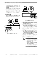
Reviews: