COPYRIGHT © 2001 CANON INC. CLC1000/1000S/3100 REV.2 MAY 2001 PRINTED IN JAPAN (IMPRIME AU JAPON)
4-63
4. MECHANICAL SYSTEM
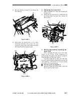
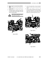
4. Removing the Lens Scanner Motor
(M4)
1)
Make preparations for parts associated with
the laser unit.
2)
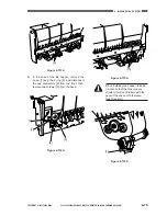
Disconnect the two connectors (J03 and J04)
on the laser scanner motor driver PCB; then,
remove the three screws [2] (M4) on the laser
scanner motor assembly.
3)
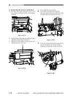
Feed the harness [3] of the connector
removed in step 2) under the laser scanner
motor.
4)
Lift the laser scanner motor [4], and
disconnect the two connectors [5]; at this time,
work paying attention to the dust-proofing
glass of the motor assembly and the lens
found on the left and the right of the motor.
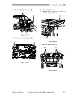
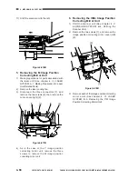
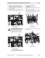
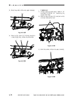
Figure 4-612A
Do not remove the M3 screw used
to keep the cover in place.
[1]
[2]
Figure 4-613A
Figure 4-614A
[4]
[3]
[5]
Summary of Contents for Vizcam 1000
Page 12: ......
Page 30: ......
Page 44: ......
Page 86: ......
Page 254: ......
Page 372: ......
Page 374: ......
Page 418: ......
Page 438: ......
Page 442: ......
Page 754: ......
Page 764: ......
Page 766: ......
Page 840: ...0501GR PRINTED IN JAPAN IMPRIME AU JAPON This publication is printed on 100 reprocessed paper...

