7-134
COPYRIGHT © 2001 CANON INC. CANON CLC1000/1000S/3100 REV.2 MAY 2001 PRINTED IN JAPAN (IMPRIME AU JAPON)
7. TROUBLESHOOTING IMAGE FAULTS/MALFUNCTIONS
46
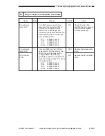
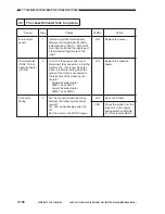
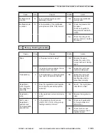
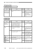
The fixing heater fails to turn ON.
Cause
Connector
Thermal switch
(THS1, THS2)
Thermistor
(THM1, THM2)
Upper heater
(H1)
Lower heater
(H2)
AC harness
Step
1
2
3
4
5
6
Checks
Are the fixing drawer connectors
J6410 and J6019 and the connec-
tors J2804 and J2808 on the AC
driver PCB connected?
Draw out the fixing unit, and set the
meter to the
×
1
Ω
range. Does the
index of the meter swing when the
probe of the meter is connected to
the terminal of the following connec-
tors of the fixing drawer connector
(J6410)?
J6410-1 and -4
J6410-5 and -8
Is there electrical continuity in the
thermal switch?
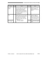
Set the meter to the
×
1
Ω
range.
Does the index of the meter swing
when the probe of the meter is
connected to the following connector
of the fixing drawer connector
(J6019)?
J6019B-7 and -5
J6019B-7 and -6
Does the index of the meter swing
when the probe of the meter is
connected to both terminals of the
upper heater?
Does the index of the meter swing
when the probes are connected to
both ends of the lower heater?
Yes/No
NO
YES
NO
YES
NO
NO
YES
Action
Re-connect them.
Go to step 8.
Replace the thermal
switch.
Replace the thermistor.
Check the installation of
the heater; if normal,
replace the upper heater.
Check the installation of
the heater; if normal,
replace the lower heater.
Check the AC harness
inside the fixing assem-
bly.
Summary of Contents for Vizcam 1000
Page 12: ......
Page 30: ......
Page 44: ......
Page 86: ......
Page 254: ......
Page 372: ......
Page 374: ......
Page 418: ......
Page 438: ......
Page 442: ......
Page 754: ......
Page 764: ......
Page 766: ......
Page 840: ...0501GR PRINTED IN JAPAN IMPRIME AU JAPON This publication is printed on 100 reprocessed paper...

