4. MECHANICAL SYSTEM
4-64
COPYRIGHT © 2001 CANON INC. CANON CLC1000/1000S/3100 REV.2 MAY 2001 PRINTED IN JAPAN (IMPRIME AU JAPON)
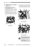
B. Image Position Correcting
Mirror Unit
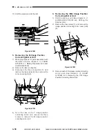
1. Removing the Y Image Position
Correcting Mirror Unit
1)
Make preparations for parts associated with
the laser unit (See chapter 4. VI. LASER
SYSTEM, A-1. Making Preparation for Laser
Unit-Related Parts).
2)
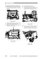
Remove the two cable mounting screws [1]
and the cable clamp [2]; then, remove the two
cover mounting screws [3], and remove the
image position correcting mirror cover (right)
[4].
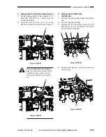
3)
Disconnect the two connectors [5], and
remove the five screws [6]; then, remove the Y
image position correcting mirror unit [7]. (Take
care not to drop the washers from the screws.)
Figure 4-601B
Figure 4-602B (rear)
Figure 4-603B (front)
[2]
[1]
[2]
[1]
[2]
[3]
[3]
[4]
[5]
[6]
<A>
[6]
[7]
[6]
[6]
[6]
<A>
Never remove the screw <A> used
to keep the butting plate of the im-
age position correction mirror unit in
place. Otherwise, the position of the
mirror unit will be lost.
Summary of Contents for Vizcam 1000
Page 12: ......
Page 30: ......
Page 44: ......
Page 86: ......
Page 254: ......
Page 372: ......
Page 374: ......
Page 418: ......
Page 438: ......
Page 442: ......
Page 754: ......
Page 764: ......
Page 766: ......
Page 840: ...0501GR PRINTED IN JAPAN IMPRIME AU JAPON This publication is printed on 100 reprocessed paper...


