3. OPERATION AND TIMING
COPYRIGHT © 2001 CANON INC. CANON CLC1000/1000S/3100 REV.2 MAY 2001 PRINTED IN JAPAN (IMPRIME AU JAPON)
3-82
5. Correcting a Discrepancy in the
Main Scanning Direction
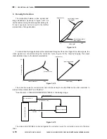
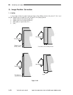
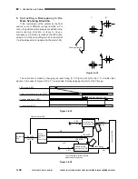
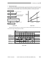
If the coordinates of the centers at the front
and the rear are different (in Figure 3-434,
∆
Y is
not 0), the position where images are started in the
main scanning direction is likely to have a
discrepancy. Correction is made so that
∆
Y will be
closer to 0. (In the case of Figure 3-434, the start of
Y will be delayed to correspond to the start of M.)
Figure 3-434
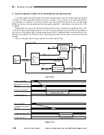
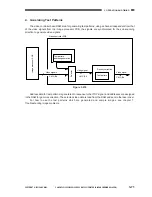
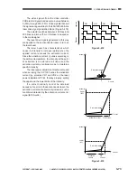
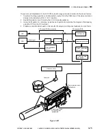
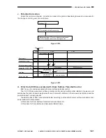
The correction is made by changing the read timing (T1 in Figure 3-435) for the Y, C, and Bk video
signals. In the case of Figure 3-434, T1 is extended, thereby delaying the start of the Y image.
Figure 3-435
Figure 3-436
Y BD signal (YBD)
Y main scanning direction sync signal (YSYNC*)
Y read enable signal (YRE*)
Y video signal (YVD)
Effective pixels on CCD
T1
Y,M
Y,M
C,Bk
C,Bk
Memory for main
scanning sync (FIFO)
Memory for main
scanning sync (FIFO)
BD signal
Y,M,C,Bk
BD detection
PCB
Video signal
Video signal
Video controller PCB
Laser driver PCB
WE
WE
CRE, BkRE
YRE, MRE
The read timing is varied at points
indicated by broad arrows.
Clock
generation
for
sync control
M
Y
Y
Y
Feeding direction
Summary of Contents for Vizcam 1000
Page 12: ......
Page 30: ......
Page 44: ......
Page 86: ......
Page 254: ......
Page 372: ......
Page 374: ......
Page 418: ......
Page 438: ......
Page 442: ......
Page 754: ......
Page 764: ......
Page 766: ......
Page 840: ...0501GR PRINTED IN JAPAN IMPRIME AU JAPON This publication is printed on 100 reprocessed paper...

