7-13
COPYRIGHT © 2001 CANON INC. CANON CLC1000/1000S/3100 REV.2 MAY 2001 PRINTED IN JAPAN (IMPRIME AU JAPON)
7. TROUBLESHOOTING IMAGE FAULTS/MALFUNCTIONS
B. Original Illuminating System
1
When Replacing the Scanning
Lamp, Standard White Plate, the
glass retainer left Lamp Regula-
tor, Reflecting Lamp Cover, or
Analog Processor PCB
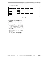
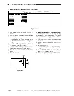
1) Execute data reading FUNC > CCD > AUTO-
ADJ in service mode.
2
Routing the Scanner Cable
• You must keep the mirror positioning tool
(FY9-3002-000) near at hand before routing
the scanner cable.
1) Remove the upper rear left cover and the
reader unit rear cover.
2) Remove the control panel.
3) Remove the vertical size plate and the glass
retainer right, and remove the copyboard
glass.
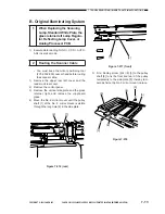
4) Move the No. 2 mirror mount until the pulley
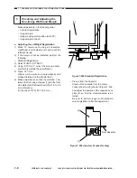
shaft [1] of the No. 2 mirror mount is visible
through the long hole [2] in the side plate.
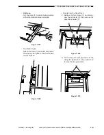
[1]
[2]
Figure 7-216 (rear)
[1]
[2]
Figure 7-217 (front)
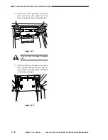
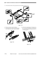
5) Fit a binding screw (M4
×
8) [3] to the pulley
shaft [4] to fix the front and rear of the pulley
temporarily to the side plate [5], thereby tem-
porarily fixing the No. 2 mirror mount in place.
[5]
[4]
[3]
[5]
[3]
[4]
Figure 7-218
Summary of Contents for Vizcam 1000
Page 12: ......
Page 30: ......
Page 44: ......
Page 86: ......
Page 254: ......
Page 372: ......
Page 374: ......
Page 418: ......
Page 438: ......
Page 442: ......
Page 754: ......
Page 764: ......
Page 766: ......
Page 840: ...0501GR PRINTED IN JAPAN IMPRIME AU JAPON This publication is printed on 100 reprocessed paper...

