3. OPERATION AND TIMING
COPYRIGHT © 2001 CANON INC. CANON CLC1000/1000S/3100 REV.2 MAY 2001 PRINTED IN JAPAN (IMPRIME AU JAPON)
3-34
E. Controlling the Intensity of the Scanning Lamp
1. Outline
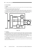
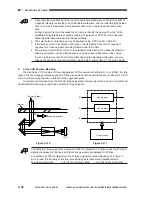
Figure 3-207 shows the circuit used to control the intensity of the scanning lamp, and the circuit has the
following functions:
1.Turns ON/OFF the scanning lamp.
2.Checks ON/OFF state of the scanning lamp.
3.Controls the intensity of the scanning lamp.
• The circuit controls the scanning lamp so that the intensity is kept to a specific level against
fluctuations in voltage.
Figure 3-207
2. Operations
a.
Turning ON/OFF the Scanning Lamp
The lamp regulator drive circuit turns OFF when LAON=0, causing the intensity control circuit and then
the scanning lamp (LA5) to turn OFF.
When LAON=1, the lamp regulator drive circuit turns ON to activate the intensity control circuit, thereby
turning ON the scanning lamp (LA5).
Lamp regulator
Reader
controller PCB
Rectifier circuit
Thermal
switch
Scanning lamp
LA5
TP 6
(175ºC)
ON detection signal
PWM
RelayRL1
Relay
drive circuit
Fu
24V
J131
-1
J135
-1
J12
-5
J1305A
-7 LAERR
-8 LAON
AC power
supply
-4
-3
-4
-9 LINT
-3
-10
-2
24V
-11
-1
Lamp regulator
drive circuit
Lamp ON
detection circuit
Timer
circuit
Switching
circuit
Intensity control circuit
Summary of Contents for Vizcam 1000
Page 12: ......
Page 30: ......
Page 44: ......
Page 86: ......
Page 254: ......
Page 372: ......
Page 374: ......
Page 418: ......
Page 438: ......
Page 442: ......
Page 754: ......
Page 764: ......
Page 766: ......
Page 840: ...0501GR PRINTED IN JAPAN IMPRIME AU JAPON This publication is printed on 100 reprocessed paper...


