COPYRIGHT © 2001 CANON INC. CANON CLC1000/1000S/3100 REV.2 MAY 2001 PRINTED IN JAPAN (IMPRIME AU JAPON)
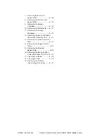
D. Duplexing Unit .................................. 4-37
1. Removing the Duplexing Unit .... 4-37
2. Removing the Duplexing
Assembly Feeding Roller .......... 4-37
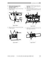
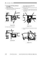
E. Pre-Fixing Feeding
Assembly ......................................... 4-38
1. Removing the Pre-Fixing
Feeding Assembly .................... 4-38
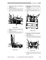
F.
Pre-Duplexing Feeding Assembly ... 4-38
1. Removing the Pre-Duplexing
Feeding Assembly .................... 4-38
G. Delivery/Reversing Assembly .......... 4-40
1. Removing the Delivery/
Reversing Assembly ................. 4-40
2. Removing the Fixing
Separation Claw ....................... 4-40
IV.
TRANSFER UNIT .................................. 4-42
A. Transfer Unit .................................... 4-42
1a. Removing the Transfer Blade ... 4-42
1b. Cleaning the Transfer Blade ...... 4-43
2. Opening the Transfer Belt
Assembly .................................. 4-43
3. Removing the Transfer Belt ...... 4-45
4. Installing the Transfer Belt ......... 4-49
5. Removing the Transfer Belt
Swing Motor (M13) ................... 4-50
6. Removing the Transfer Belt
Assembly .................................. 4-50
7. Removing the Transfer Belt
Motor (M14) .............................. 4-51
8. Installing the Transfer Belt
Motor ........................................ 4-51
9. Removing the Internal Static
Eliminating Roller ...................... 4-51
10. Removing the Grounding Roller ... 4-52
11. Cleaning the Grounding Roller ... 4-52
12. Cleaning the Transfer Belt
Seam Detecting Sticker ............ 4-52
13. Cleaning the Transfer Belt
Home Position Sensor .............. 4-53
B. Transfer Belt Mount .......................... 4-53
1. Removing the Transfer
Cleaning Blade ......................... 4-53
2. When Replacing the Transfer
Cleaning Blade ......................... 4-53
3. Removing the Transfer
Cleaning Web. .......................... 4-54
4. Removing the Oil
Removing Roller ....................... 4-54
5. Removing the Polishing Roller ... 4-54
C. Replacing the Separation Paper
Guides Static Eliminating Wire ........ 4-55
V.
EXPOSURE SYSTEM ........................... 4-56
A. Original Exposure System ............... 4-56
1. Removing the Scanning Lamp ...... 4-56
2. Orientation of the Scanning
Lamp ........................................ 4-56
3. Removing the Standard
White Plate ............................... 4-57
4. Removing the Lens Mount Cover,
CCD Cover, and CCD Unit ....... 4-57
5. Removing the Scanner Cover .. 4-58
B. Pre-Exposure System ..................... 4-59
1. Removing the Pre-Exposure
System ..................................... 4-59
VI.
LASER SYSTEM ................................... 4-60
A. Laser Unit ........................................ 4-60
1. Making Preparations for
Laser Unit-Related Parts .......... 4-60
2. Removing the Laser Unit .......... 4-61
3. Points to Note When Installing
the Laser Unit ........................... 4-61
4. Removing the Lens Scanner
Motor (M4) ................................ 4-63
B. Image Position Correcting
Mirror Unit ........................................ 4-64
1. Removing the Y Image Position
Correcting Mirror Unit ............... 4-64
2. Points to Note When Installing the Y
Image Correcting Mirror Unit .... 4-65
3. Removing and Installing the
Motors for the Y Image
Correcting Mirror ....................... 4-65
4. Shifting the Scanner Unit .......... 4-66
5. Removing the M Image Position
Correcting Mirror Unit ............... 4-68
6. Removing the C/BK Image Position
Correcting Mirror Unit ............... 4-68
7. Removing the Dust-Proofing
Glass ........................................ 4-69
8. Removing the BD Unit .............. 4-69
VII. HOPPER SYSTEM ................................ 4-72
A. Hopper Assembly ............................ 4-72
1. Removing the Hopper
Assembly .................................. 4-72
2. Keeping the Hopper Assembly
from Tumbling Down ................. 4-74
3. Removing the Hoppers ............. 4-74
4. Removing the Toner Level
Sensor ...................................... 4-76
VIII. CHARGING SYSTEM ............................ 4-78
A. Primary Charging Assembly ............ 4-78
1. Outline ...................................... 4-78
2. Removing the Primary
Charging Assembly .................. 4-78
3. Removing the Grid Plate ........... 4-78
Summary of Contents for Vizcam 1000
Page 12: ......
Page 30: ......
Page 44: ......
Page 86: ......
Page 254: ......
Page 372: ......
Page 374: ......
Page 418: ......
Page 438: ......
Page 442: ......
Page 754: ......
Page 764: ......
Page 766: ......
Page 840: ...0501GR PRINTED IN JAPAN IMPRIME AU JAPON This publication is printed on 100 reprocessed paper...


