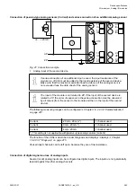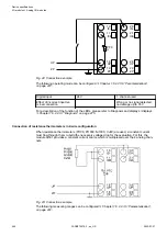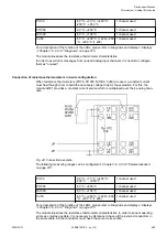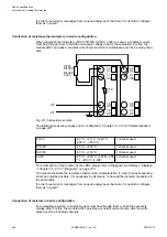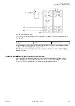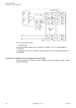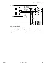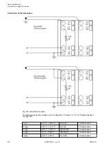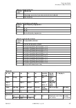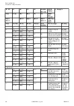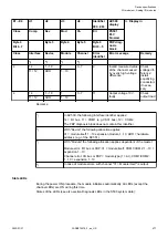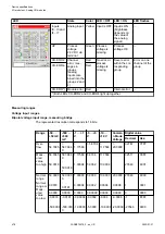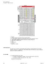
For a description of the function of the LEDs, please refer to Diagnosis and displays / displays
Chapter 1.6.2.2.3.7 “Diagnosis” on page 475
The module linearizes the thermocouple characteristics. It supports the following possibilities of
temperature compensation and handling with cold junctions:
Internal compensation
An internal temperature sensor which is located next to the terminal unit is used to detect the
temperature of the cold junction. So the compensating cables must be connected directly to the
terminal unit, where the cold junction is located.
The setting "Internal compensation (default)" for the parameter "Compensation channel" should
be selected.
To get more precise temperature measurements, the use of an external com-
pensation method is recommended.
External compensation with temperature input
The temperature for the cold junction can be determinated externally.
A measured or known temperature value (e.g. ambient temperature in the cabinet) is transferred
to the module via the output data word to all required channels. The possible temperature range
is from -25 °C to +60 °C and is monitored by the AI531.
The setting "External with temperature value" for the parameter "Compensation channel" should
be selected.
External compensation with compensation box
A compensation box balances the temperature difference between the cold junction and the
reference temperature by generating a bridge voltage. The reference temperature is transferred
via the output data word.
The compensation box must fit to the type of thermocouple and is located at the end of the
compensating cables, where the cold junction is located. The cabling to the AI531 can be
carried out with normal cables. The operating manual of the compensation box also has to be
considered.
The setting "External with temperature value" for the parameter "Compensation channel" should
be selected.
External compensation with flanking channel
A flanking channel of the same input group can be used for compensation, e. g. for channel
3, the channels 0, 1 and 2 can be selected as reference channels. The type of sensor for the
reference channel can be selected in the parameters for the flanking channel. For example, a
RTD sensor which is located next to the thermocouple terminal can be used as reference point
for other channels.
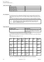
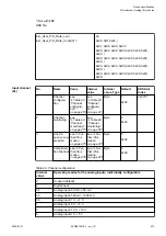
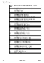
The setting "Channel x" for the parameter "Compensation channel" should be selected. Refer
to Channel configuration
Chapter 1.6.2.2.3.6 “Parameterization” on page 472
for possible
settings.
In order to avoid error messages from unused analog input channels, it is useful to configure
them as "unused".
Device specifications
I/O modules > Analog I/O modules
2022/01/31
3ADR010278, 3, en_US
471


