
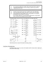

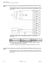
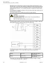

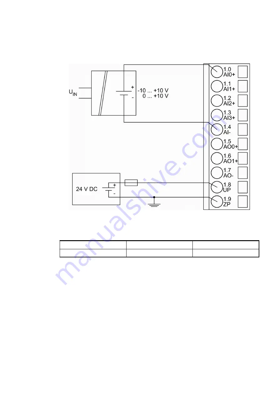
Connection of active-type analog sensors (Voltage) with galvanically isolated power supply to the analog
inputs
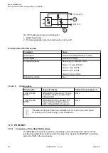
The following figure shows the connection of active-type analog sensors (voltage) with galvani-
cally isolated power supply to the analog input AI0. Proceed with the analog inputs AI1 to AI3 in
the same way.
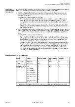
The following measuring ranges can be configured
Chapter 1.7.5.2.7 “Parameterization”
Chapter 1.7.5.2.9.1 “Input ranges voltage, current and digital input”
Voltage
0 V...10 V
1 channel used
Voltage
-10 V...+10 V
1 channel used
The function of the LEDs is described under Diagnosis and displays / Displays
1.7.5.2.8 “Diagnosis and state LEDs” on page 821
.
To avoid error messages from unused analog input channels, configure them as "unused".
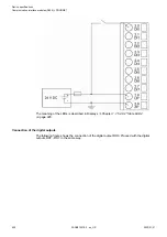
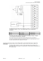
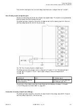
Connection of active-type analog sensors (Current) with galvanically isolated power supply to the analog
inputs
The following figure shows the connection of active-type analog sensors (current) with galvani-
cally isolated power supply to the analog input AI0. Proceed with the analog inputs AI1 to AI3 in
the same way.
Device specifications
Communication interface modules (S500) > PROFINET
2022/01/31
3ADR010278, 3, en_US
806