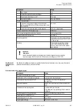
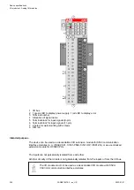
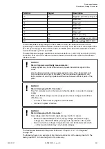


NOTICE!
Attention:
All I/O channels (digital and analog) are protected against reverse polarity,
reverse supply, short circuit and continuous overvoltage up to 30 V DC.
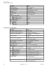
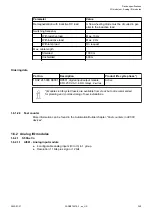
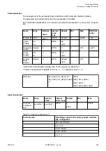
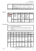
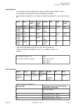
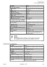
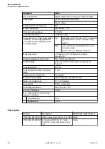
Technical data of the analog inputs
Parameter
Value
Number of channels per module
4 individually configurable voltage or current
inputs
Distribution of channels into groups
1 (4 channels per group)
Resolution
Unipolar
Voltage: 0 V...+5 V; 0 V...+10 V: 12 bits
Current 0 mA...20 mA; 4 mA...20 mA: 12 bits
Bipolar
Voltage -2.5 V...+2.5 V; -5 V...+5 V: 11 bits plus
sign
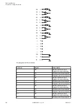
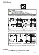
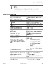
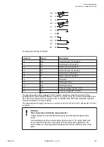
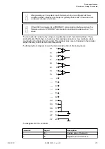
Connection of the signals I0- to I3-
Terminals 3, 6, 9, 12
Connection of the signals I0+ to I3+
Terminals 2, 5, 8, 11
Input type
Differential
Galvanic isolation
No galvanic isolation between the inputs and
the I/O bus
Common mode input range
Signal voltage plus common mode voltage
must be within
±
12 V
Indication of the input signals
No
Channel input resistance
Voltage: > 1 M
W
Current: ca. 250
W
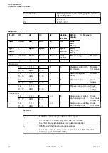
Conversion error of the analog values
caused by non-linearity, adjustment error
at factory and resolution within the normal
range
Typ.
±
0.5 % of full scale (voltage)
±
0.5 % of full scale (current 0
mA...20 mA)
±
0.7 % of full scale (current 4
mA...20 mA)
at 25 °C
Max.
±
2 % of full scale (all ranges)
at 0 °C...60 °C or EMC disturbance
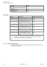
Time constant of the input filter
Voltage: 300
µ
s
Current: 300
µ
s
Relationship between input signal and hex
code
Chapter 1.6.2.1.1.8 “Measuring ranges”
Analog to digital conversion time
Typ. 500
µ
s per channel
Unused inputs
Can be left open and should be configured as
"unused"
Input data length
8 bytes
Overvoltage protection
Yes, up to 30 V DC only for voltage input
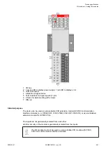
Device specifications
I/O modules > Analog I/O modules
2022/01/31
3ADR010278, 3, en_US
359