


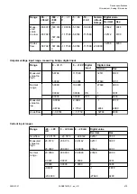


Pt100
-50 °C...+70 °C / +400 °C;
-200 °C...+850 °C
1 channel used
Pt1000
-50 °C...+400 °C
1 channel used
Ni1000
-50 °C...+150 °C
1 channel used
Cu50
-50 °C...+200 °C (1.426); -200
°C...+200 °C (1.428)
1 channel used
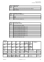
For a description of the function of the LEDs, please refer to Diagnosis and displays / displays
Chapter 1.6.2.2.3.7 “Diagnosis” on page 475
The module linearizes the resistance thermometer characteristics.
In order to avoid error messages from unused analog input channels, it is useful to configure
them as "unused".
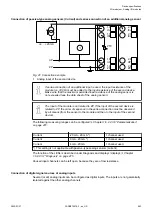
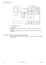
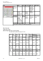
Connection of resistance thermometers in 3-wire configuration
When resistance thermometers (Pt100, Pt1000, Ni1000, Cu50) are used, a constant current
must flow through them to build the necessary voltage drop for the evaluation. For this, the
module AI531 provides a constant current source which is multiplexed over the 4 analog chan-
nels.
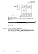
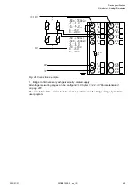
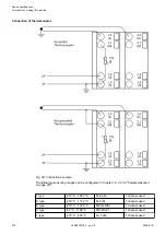
Fig. 44: Connection example
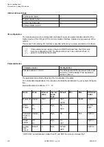
The following measuring ranges can be configured
Chapter 1.6.2.2.3.6 “Parameterization”
Pt100
-50 °C...+70 °C / +400 °C;
-200 °C ... +850 °C
1 channel used
Pt1000
-50 °C...+400 °C
1 channel used
Ni1000
-50 °C...+150 °C
1 channel used
Cu50
-50 °C...+200 °C (1.426); -200
°C...+200 °C (1.428)
1 channel used
For a description of the function of the LEDs, please refer to Diagnosis and displays / displays
Chapter 1.6.2.2.3.7 “Diagnosis” on page 475
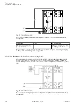
The module linearizes the resistance thermometer characteristics. In order to keep measuring
errors as small as possible, it is necessary by all means to have all the involved conductors in
the same cable. All the conductors must have the same cross section.
Device specifications
I/O modules > Analog I/O modules
2022/01/31
3ADR010278, 3, en_US
465