
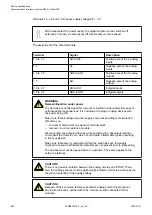

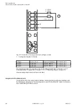
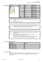

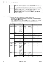
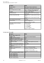

Interface
PIN
Signal
Description
1
TxD+
Transmit data +
2
TxD-
Transmit data -
3
RxD+
Receive data +
4
NC
Not connected
5
NC
Not connected
6
RxD-
Receive data -
7
NC
Not connected
8
NC
Not connected
Shield
Cable shield
Functional earth
In corrosive environment, please protect unused connectors using the TA535
accessory.
Not supplied with this device.
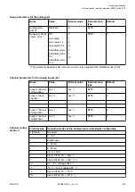
For further information regarding wiring and cable types see chapter Ethernet
Chapter 2.6.4.7 “Ethernet connection details” on page 997.
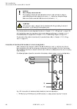
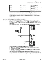
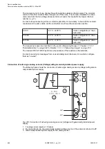
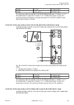
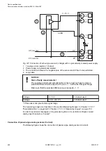
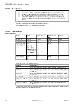
The EtherCAT network differentiates between input-connectors (IN) and output-
connectors (OUT):
At the EtherCAT slaves (communication interface modules), the ETH1-con-
nector is IN and the ETH2-connector is OUT.
At the EtherCAT master (communication module), the ETHCAT1 connector has
to be used. The ETHCAT2 connector is reserved for future extensions.
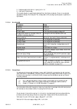
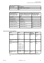
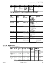
1.7.3.1.4 Internal data exchange
Parameter
Value
Digital inputs (bytes)
1
Digital outputs (bytes)
1
Analog inputs (words)
4
Analog outputs (words)
2
1.7.3.1.5 Addressing
The Ethernet bus module CI511-ETHCAT does not consider the position of the rotary switches
at the front side of the module. The function of the rotary switches is reserved for future
expansions.
Pin assignment
Device specifications
Communication interface modules (S500) > EtherCAT
2022/01/31
3ADR010278, 3, en_US
693