


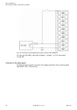
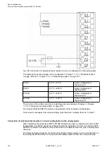

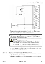
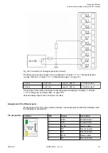

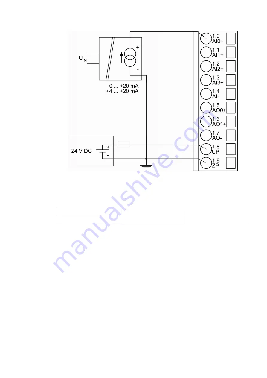
Fig. 142: Connection of active-type analog sensors (current) with galvanically isolated power
supply to the analog inputs
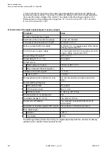
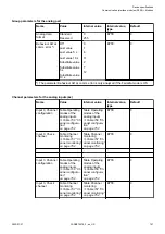
The following measuring ranges can be configured
Chapter 1.7.4.1.7 “Parameterization”
Chapter 1.7.4.1.9 “Measuring ranges” on page 761
:
Current
0...20 mA
1 channel used
Current
4...20 mA
1 channel used
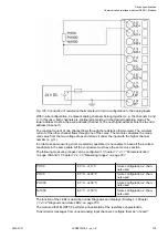
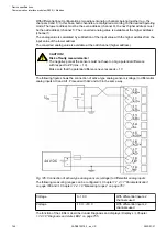
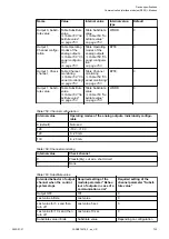
The function of the LEDs is described under Diagnosis and displays / Displays
1.7.4.1.8 “Diagnosis and state LEDs” on page 755
.
Unused input channels can be left open-circuited, because they are of low resistance.
To avoid error messages through unused analog input channels in measuring range 4...20 mA,
these channels should be configured as "Not used".
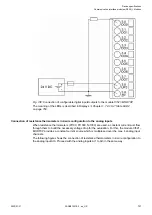
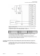
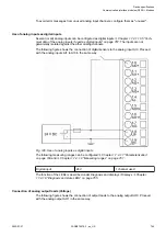
Connection of active-type analog sensors (Voltage) with no galvanically isolated power supply to the
analog inputs
The following figure shows the connection of active-type analog sensors (voltage) with no
galvanically isolated power supply to the analog input AI0. Proceed with the analog inputs AI1 to
AI3 in the same way.
Device specifications
Communication interface modules (S500) > Modbus
2022/01/31
3ADR010278, 3, en_US
741