


WARNING!
Removal/Insertion under power
The devices are not designed for removal or insertion under power. Because of
unforeseeable consequences, it is not allowed to plug or unplug devices with
the power being ON.
Make sure that all voltage sources (supply and process voltage) are switched
off before you
–
connect or disconnect any signal or terminal block
–
remove, mount or replace a module.
Disconnecting any powered devices while energized in a hazardous location
could result in an electric arc, which could create a flammable ignition resulting
in fire or explosion.
Make sure that power is removed and that the area has been thoroughly
checked to ensure that flammable materials are not present prior to proceeding.
The devices must not be opened when in operation. The same applies to the
network interfaces.
NOTICE!
Risk of damaging the PLC modules!
Overvoltages and short circuits might damage the PLC modules.
–
Make sure that all voltage sources (supply voltage and process supply
voltage) are switched off before you begin with operations on the system.
–
Never connect any voltages or signals to reserved terminals (marked with
---). Reserved terminals may carry internal voltages.
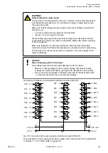
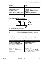
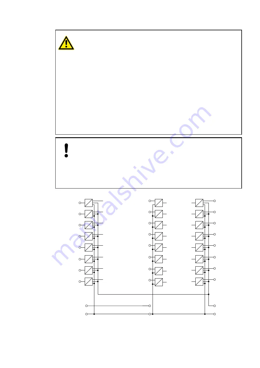
Connection of CANopen communication interface module CI582-CN:
4.0 DO8
4.1 DO9
4.2 DO10
4.3 DO11
4.4 DO12
4.5 DO13
4.6 DO14
4.7 DO15
DI8
3.0
DI9
3.1
DI10 3.2
DI11 3.3
DI12 3.4
DI13 3.5
DI14 3.6
DI15 3.7
2.8
2.9
UP +24 V
ZP 0 V
3.8
3.9
4.9
4.8
UP3 +24 V
ZP 0 V
DC0 2.0
DC1 2.1
DC2 2.2
DC3 2.3
DC4 2.4
DC5 2.5
DC6 2.6
DC7 2.7
Fig. 116: Connection of the communication interface module CI582-CN
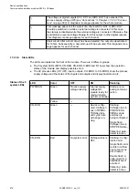
For a description of the meaning of the LEDs, please refer to the section for the state LEDs
Chapter 1.7.2.3.9 “State LEDs” on page 674
.
Device specifications
Communication interface modules (S500) > CANopen
2022/01/31
3ADR010278, 3, en_US
665