
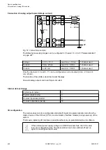


The modules are plugged on an I/O terminal unit
Chapter 1.5.2 “TU515, TU516, TU541 and
TU542 for I/O modules” on page 126
. Properly position the modules and press until they lock
in place. The terminal units are mounted on a DIN rail or with 2 screws plus the additional
accessory for wall mounting (TA526
Chapter 1.8.2.6 “TA526 - Wall mounting accessory”
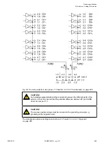
The connection of the I/O channels is carried out using the 40 terminals of the I/O terminal unit.
I/O modules can be replaced without re-wiring the terminal units.
The terminals 1.8, 2.8, 3.8 and 4.8 as well as 1.9, 2.9, 3.9 and 4.9 are electrically intercon-
nected within the I/O terminal units and have always the same assignment, irrespective of the
inserted module:
Terminals 1.8, 2.8, 3.8 and 4.8: process voltage UP = +24 V DC
Terminals 1.9, 2.9, 3.9 and 4.9: process voltage ZP = 0 V DC
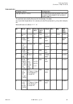
The assignment of the other terminals:
Terminals
Signal
Description
1.0 to 1.3
I0- to I3-
Negative poles of the 4 analog
inputs
2.0 to 2.3
I0+ to I3+
Positive poles of the 4 analog
inputs
3.0 to 3.3
O0- to O3-
Negative poles of the 4 analog
outputs
4.0 to 4.3
O0+ to O3+
Positive poles of the 4 analog
outputs
The negative poles of the analog inputs are connected to each other to form an
"Analog Ground" signal for the module.
The negative poles of the analog outputs are connected to each other to form
an "Analog Ground" signal for the module.
There is no galvanic isolation between the analog circuitry and ZP/UP. There-
fore, the analog sensors must be galvanically isolated in order to avoid loops via
the ground potential or the supply voltage.
Because of their common reference potential, analog current inputs cannot
be circuited in series, neither within the module nor with channels of other
modules.
For the open-circuit detection (cut wire), each analog input channel is pulled up
to "plus" by a high-resistance resistor. If nothing is connected, the maximum
voltage will be read in then.
Device specifications
I/O modules > Analog I/O modules
2022/01/31
3ADR010278, 3, en_US
502