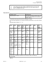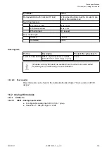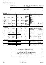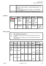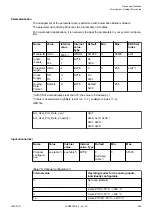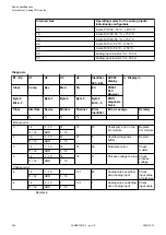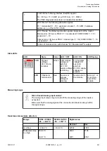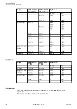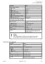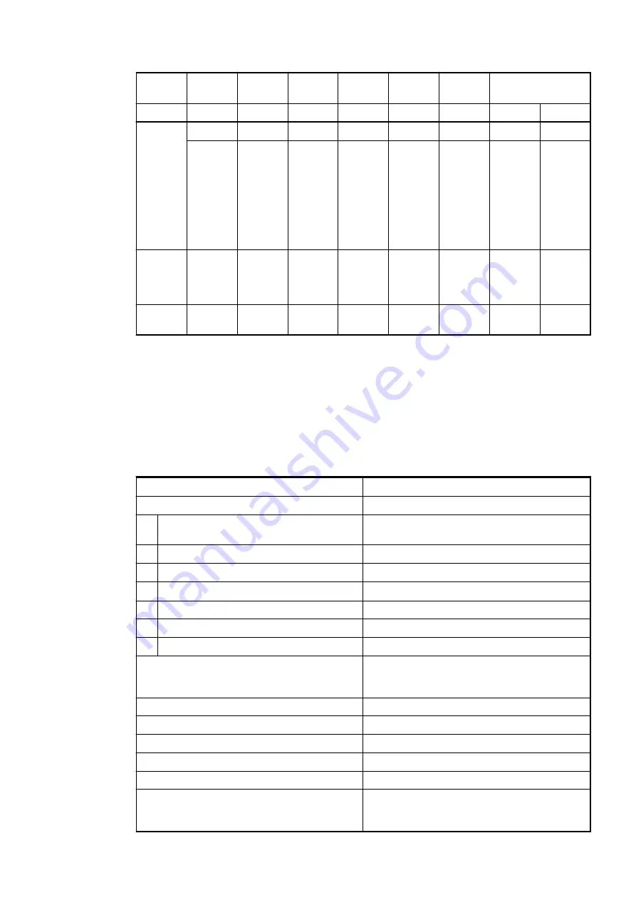
Range
-2.5 ...
+2.5 V
-5 ... +5
V
0 ... 5 V
0 ... 10 V 0 ... 20
mA
4 ... 20
mA
Digital value
Decimal Hex.
Normal
range or
meas-
ured
value too
low
0.0000
0.0000
0.0000
0.0000
0
4
0
0000
:
-0.0014
:
:
:
-2.5000
:
-0.0029
:
:
:
-5.0000
3.9942
:
:
0
-10
-16
-4864
-6912
:
-27648
FFF6
FFF0
ED00
E500
:
9400
Meas-
ured
value too
low
-2.5014
:
-2.9398
-5.0029
:
-5.8795
-27664
:
-32512
93F0
:
8100
Under-
flow
<-2.9398 <-5.8795 <-0.0300 <-0.0600 <-0.1200 <-0.1200 -32768
8000
The represented resolution corresponds to 12 bits respectively 11 bits plus sign.
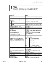
Technical data
The System Data of AC500-eCo apply
Chapter 2.5.1 “System data AC500-eCo V3”
Only additional details are therefore documented below.
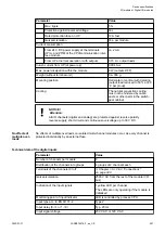
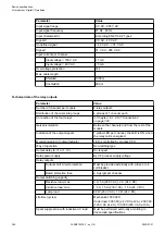
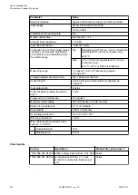
Parameter
Value
Process supply voltage L+
Connections
Terminal 19 for L+ (+24 V DC) and terminal 20
for M (0 V)
Rated value
24 V DC
Current consumption via L+ terminal
0.1 A
Inrush current (at power up)
0.05 A
2
s
Max. ripple
5 %
Protection against reversed voltage
Yes
Protection fuse for L+
Recommended
Current consumption from 24 V DC power
supply at the terminals UP/L+ and ZP/M of the
CPU/communication interface module
Ca. 10 mA
Galvanic isolation
No
Surge-voltage (max.)
35 V DC for 0.5 s
Max. power dissipation within the module
2.7 W
Weight
Ca. 120 g
Mounting position
Horizontal or vertical
Cooling
The natural convection cooling must not be
hindered by cable ducts or other parts in the
switchgear cabinet.
Device specifications
I/O modules > Analog I/O modules
2022/01/31
3ADR010278, 3, en_US
358

