2.4.2 Mechanical encoding
18
17
16
15
14
13
12
11
10
9
8
7
6
5
4
3
2
1
Pos.
18
17
16
15
14
13
12
11
10
9
8
7
6
5
4
3
2
1
18
17
16
15
14
13
12
11
10
9
8
7
6
5
4
3
2
1
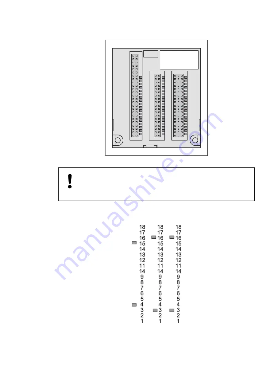
Fig. 165: Possible positions for mechanical encoding (1 to 18)
NOTICE!
Terminal units and terminal bases have a mechanical coding which prevents
modules (from) being inserted into the wrong places for cases that might result
in dangerous parasitic voltages or if modules could be destroyed.
The coding either makes it impossible to insert the module to the wrong place or blocks its
electrical function (outputs are not activated).
The following figures show the possible encodings.
Fig. 166: Encoding for processor modules with Ethernet interface
System assembly, construction and connection
Overall information (valid for complete AC500 product family) > Mechanical encoding
2022/01/31
3ADR010278, 3, en_US
914


