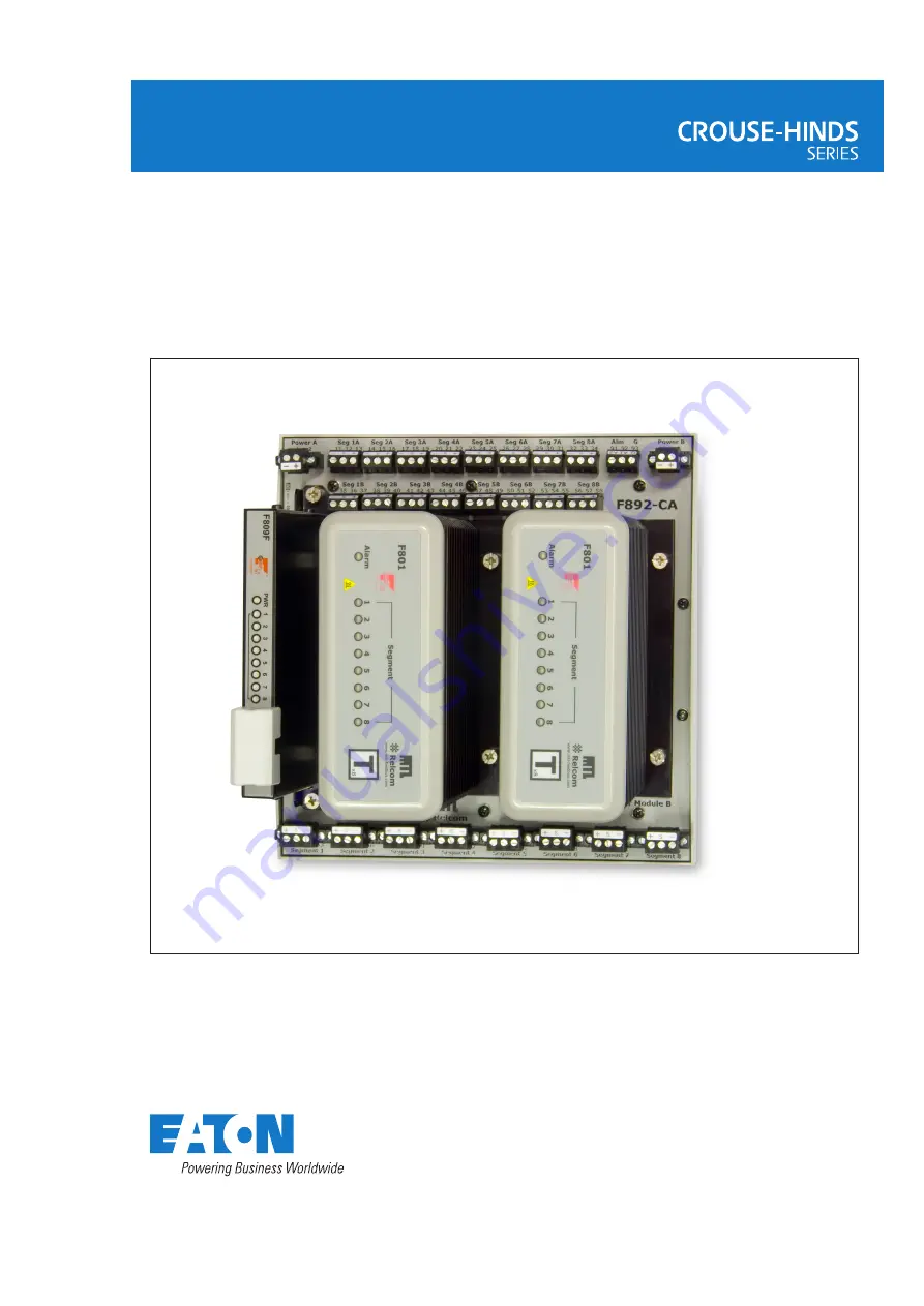
MTL F892
8 Segment Redundant Fieldbus Power Supply for use
with non-proprietary cabled systems
March 2022INM F890 Rev 1
Instruction manual
MTL fieldbus networks
DRAFT - 31st March 2022
Page 1: ...MTL F892 8 Segment Redundant Fieldbus Power Supply for use with non proprietary cabled systems March 2022 INM F890 Rev 1 Instruction manual MTL fieldbus networks...
Page 2: ...ii INM F892 Rev 1 THIS PAGE IS LEFT INTENTIONALLY BLANK...
Page 3: ...5 5 ELECTRICAL CONNECTIONS 5 5 1 DC Power Requirements 6 5 2 Power A and Power B 7 5 2 1 Redundancy 7 5 2 2 Terminator 7 5 3 Alarm Connection 7 5 4 FInal Segment Connections 8 5 5 Field Segment Connec...
Page 4: ...incorporated into each Power Module A single F801 or F802 module may be used where redundancy is not required 2 DESCRIPTION For maximum reliability the module carrier contains no components and only...
Page 5: ...is lit Redundant 24V DC nom input power is connected to the F892 CA carrier using two part pluggable connectors Field wiring connections are available with either pluggable screw terminals F892 PS or...
Page 6: ...ith a single row of eight connectors top The Diagnostic Segment Connectors were introduced on carriers with date codes after 0726 The Shield Ground Option was added with revision F 0 previous version...
Page 7: ...at DIN rail to EN50022 and uses six built in DIN clamp tabs to hold it on the rail The F801 power modules must be removed from the carrier to obtain access to the DIN rail clamp screws 4 3 1 Mounting...
Page 8: ...To remove a Power Module support the module while unscrewing the four retaining screws at its base Lift the module off the carrier connector Note Earlier versions of the module carriers do not have l...
Page 9: ...vided allowing the use of bulk power supplies with a supply range of 19 2 30VDC Input power cabling and over current protection devices must be chosen to match the current consumption An F892 system o...
Page 10: ...Power Module B connector to allow the alarm circuit to function Power must be connected to Power B terminals if live replacement of Power Module A is necessary since Power B terminals feed the Power...
Page 11: ...so only one connection should be made from the Termblock to the F892 carrier Other systems such as the ABB 800xA or the Rosemount 3420 use the power supply carrier to make the interconnection between...
Page 12: ...r the jumper The carrier is delivered with the jumper installed as shown in figure 7b As indicated in the text on the jumper the screens are isolated To tie the 8 screens together and route them to th...
Page 13: ...eg S 98 Diag Seg S 96 Diag Seg 99 Diag Seg 6 TESTING 6 1 F801 Status and Alarm LEDs The F801 or F802 Power Modules are fitted with nine LEDs eight to indicate segment status and one to signify an Alar...
Page 14: ...11 INM F892 Rev 1 8 FM CONTROL DRAWINGS...
Page 15: ...ed in place of the missing F801 or F802 module 24VDC Power Supplies may be installed in the Non hazardous area Vmax 24VDC F801 30VDC F802 24VDC Power Supply A 24VDC Power Supply A This is a Chassis Gr...
Page 16: ...clause 4 2 of EN 60079 17 b This equipment has been designed to provide protection against all the relevant additional hazards referred to in Annex II of the directive such as those in clause 1 2 7 c...
Page 17: ...ified product 9 5 Marking Each device is marked in compliance with the Directive Regulation This information applies to products manufactured during or after the year 2007 Typical certification markin...
Page 18: ...15 INM F892 Rev 1 THIS PAGE IS LEFT INTENTIONALLY BLANK...
Page 19: ...Old Mahabalipuram Road Sholinganallur Chennai 600 119 India Tel 91 0 44 24501660 24501857 Fax 91 0 44 24501463 E mail mtlindiasales eaton com ITALY MTL Italia srl Via San Bovio 3 20090 Segrate Milano...